Abstract
Keywords: Additive manufacturing; collaborative robot; 3D printing technology
Industrial robots and 3D printing are 2 two of the most prominent pillars of Industry 4.0. The usage of 3D printing as a common manufacturing method requires a concentration on improving the dimensional accuracy, a better surface quality, and higher mechanical properties of 3D printed parts [1,2]. As production shifts from prototyping to small- or medium-scale manufacturing, it becomes essential to prioritize meeting these requirements, with the goal of minimizing production time and costs. However, achieving control over specific 3D printing and reaching the desired level of accuracy simultaneously with high surface quality remains a significant challenge for both manufacturers and end users, particularly when determining optimal printing conditions that guarantee repeatability and reliability.
A critical component in establishing these optimal conditions is to consider the various influencing factors. These include the geometric specifications of the parts, the chemical composition of the filament material, the operating conditions of the 3D printers, post-printing positioning and fixing of the part, the characteristic elements of specific 3D printing techniques, the configuration and structure of the extruder assembly, and the printing parameters themselves, establishing the scope and problem to be addressed.
A review of the most used 3D printing technologies, which include stereolithography (SLA), selective laser sintering (SLS), digital light processing (DLP), multi-jet fusion (MJF), PolyJet, direct metal laser sintering (DMLS), and electron beam melting (EBM) (Figure 1), indicates that fused deposition modeling (FDM) was considered the most adequate technology in manufacturing parts due to its specific advantages [3].
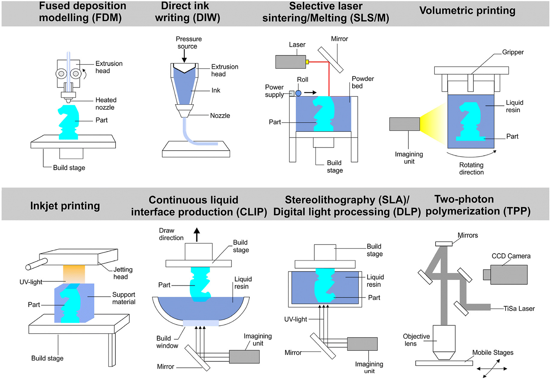
Figure 1. 3D printing methods [3]
The field of robotics is undergoing massive development and is currently undergoing a transition from conventional, solitary industrial robots to exceedingly intricate, collaborative systems [4].
Collaborative robots, also referred to as cobots, have been specifically designed and manufactured to operate alongside human personnel. Collaborative robots are equipped with safety features, such as force and torque sensors, collision detection, and compliance control, which allow them to adjust their movements to prevent accidents during interactions. One main advantage of some collaborative robots can be programmed without complex coding. Additionally, easy-to-use programming interfaces make it easy to teach tasks to operators with minimal coding experience. Also, cobots do not have sharp edges and are covered with soft materials. The operational advantages of cobots increase the area of operation, including additive manufacturing. The integration of robotics with additive manufacturing has given rise to a novel concept known as robotic-assisted additive manufacturing (RAAM). The integration of robotics and 3D printing, exemplified by RAAM, results in a production structure that combines the precision and large workspace of cobots with the vast possibilities of 3D printing. This integration allows for the manufacturing of intricate parts and the enhancement of the quality of printed components (Figure 2a).
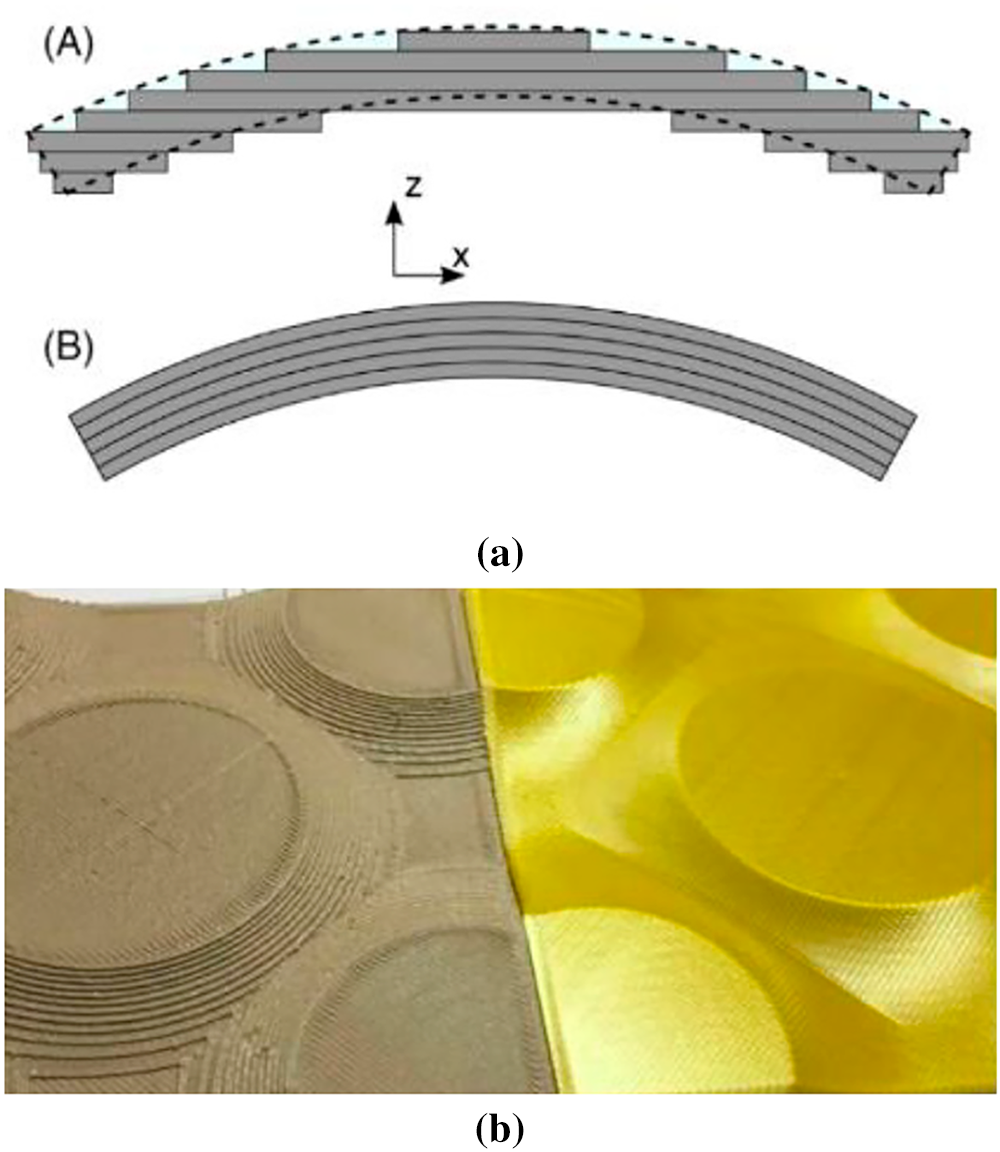
Figure 2. Different views of conventional 3D printing vs. continous robotic 3D printing: (a) transversal sections: A—planar printing; B—nonplanar/continous printing; (b) 3D views [3]
The programming of collaborative robots (cobots) is less complicated than the programming of industrial robots. The safety factor was the most important one when cobots were designed; they are adaptable and equipped with sensors that do not allow collisions with human workers. Also, there are safety protocols that stop the movements of cobots if any unplanned contact occurs. Cobots have rounded edges, and some parts are covered with soft materials. Some collaborative robots can be programmed through manual guidance, where operators can physically demonstrate tasks without complex coding. Additionally, easy-to-use programming interfaces, such as visual interfaces and drag-and-drop programming, simplify the teaching of tasks for operators with minimal coding experience. The operational advantages of cobots increase of the area operation, including additive manufacturing. The integration of robotics with additive manufacturing has given rise to a novel concept known as robotic-assisted additive manufacturing (RAAM). The integration of robotics and 3D printing, exemplified by RAAM, it results in a production structure that combines the precision and large workspace of cobots with the vast possibilities of 3D printing. This integration allows for the manufacturing of intricate parts and the enhancement of the quality of printed components (Figure 2a), [3]. Furthermore, it enables the automation of all stages of 3D printing. A specific aspect of RAAM is that allows continuous 3D printing without layer interruption, as conventional 3D printers operate (layer by layer), as a consequence of the larger number of degrees of freedom specific to articulated robots. In theory, continuous fiber leads to an increase in the mechanical properties of the printed product (Figure 2b).
The implementation of the RAAM concept poses a unique set of challenges. The implementation of RAAM necessitates a multidisciplinary approach, thereby requiring the integration of expertise from several fields, including mechanical, electrical, automation, and software engineering. Three-dimensional printing necessitates a distinct programming strategy for collaborative robots (cobots) compared to conventional robot operations, such as pick and place welding. The process entails numerous challenges, including adapting the printing extruder, identifying suitable materials, developing sophisticated control software to translate 3D models into robotic instructions, and meticulously calibrating the robot arm and extruder to ensure synchronized operation.
A particular challenge lies in the programming of the robotic arm to execute the trajectory with precision, as well as in achieving optimal material extrusion and balancing speed, precision, and material qualities.
The paper [5,6] offers new insights on performing multi-resolution 3D printing using the robotic cell consisting of two industrial robots that are used successively to print various layers with different resolutions. In this case, by communication between the two robots and a master computer, non-planar layers are achieved by accurately depositing material following a trajectory computed in Python. A more thorough examination of the intricacies of RAAM reveals the implementation of a multitasking framework, which encompasses system design, integration, and the generation of collision-free robot trajectories [7]. Most of the current research has been done on 5 and 6-DOF robots; there are several researchers who use two robots to simultaneously print large parts [8]. One impediment in the development of large DOF additive manufacturing equipment is usually the high cost involved and the need to use sophisticated control systems for trajectory control and extrusion simultaneously. Previous studies indicate that achieving consistent extrusion quality in robotic FDM systems is considerably more difficult than in conventional Cartesian printers, primarily because of the robot’s dynamic motion behavior, changing tool orientations, and the complexity of multi-axis trajectory control [7–9].
One condition imposed on robotic printing by industrial robots or cobots refers to positioning accuracy and repeatability. Research performed by [9–11] indicates that cobots, in general, present a better positioning accuracy and repeatability than conventional 3D printers that are commercially available. In general, robotic printing has a larger working area than a conventional printer, but some concerning aspects refer to the speed reached during 3D printing, which requires optimizations that decrease the drift obtained by fast alterations of motion trajectories and the excessive vibrations of the structure during printing, thus assuring the necessary position of the extruder [10].
There are two possibilities for 3D printing when using a robotic arm: a conventional one (plane-plane printing) and a non-planar/continuous one when using a three-dimensional trajectory. The aim of the experimental research is to establish the differences between the mechanical properties and precision of 3D printed parts using these two 3D printing methods. Another important aspect that must be emphasized is the usage of Carbon Fiber Composites in 3D printing, mainly in the automotive industry, for offering exceptional stiffness and strength at a low weight. For carbon fiber composites in 3D printing, thermoplastic or thermoset polymer matrices are used: PLA (polylactide), Nylon (PA), Epoxy, PEEK/PEKK (for advanced applications); Epoxy (in lamination, not in classic 3D printing). These matrices have different properties, but all must be verified under conditions of humidity and UV rays. New organic matrices based on epoxy resins with strong mechanical properties, 3D printing materials that can be cured without preliminary heating, under UV or e-beam curing, and at room temperature, possessing increased thermal and mechanical properties, and are usable in corresponding applications [12,13].
2.1. Experimental equipment and software
In order to obtain the 3D printed probes a special experimental stand was designed and constructed with special support for the UR3E robot arm from Universal Robots with a slightly atypical mounting in the upper parts of the custom support structure (Figure 3), [3]. This orientation and positioning of the cobot allows for a larger work area.
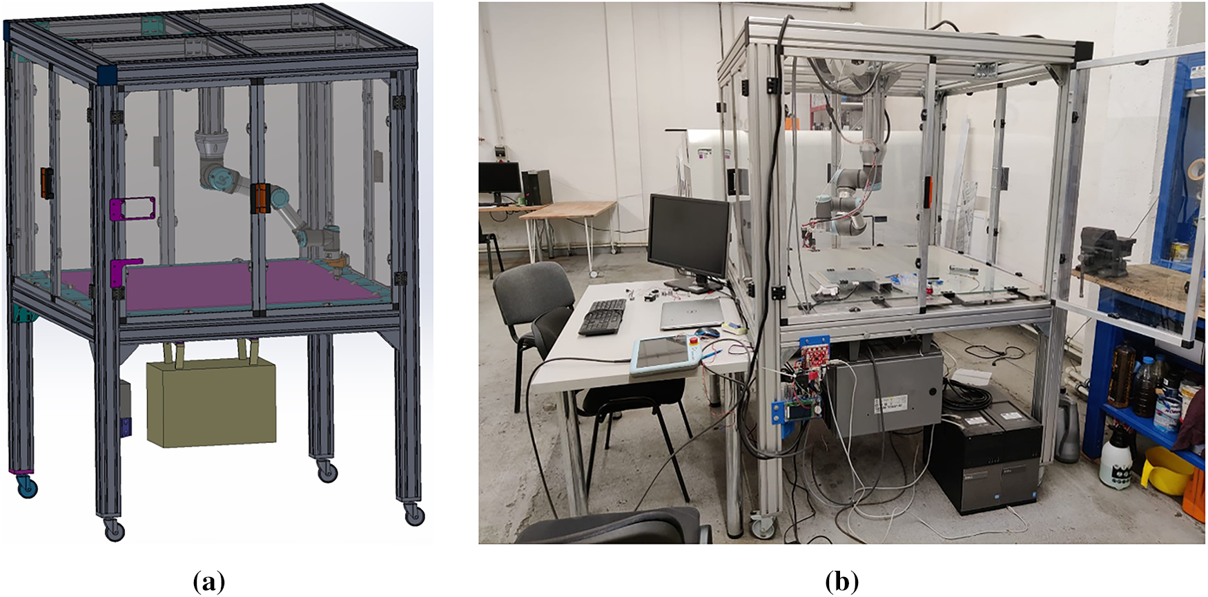
Figure 3. Experimental stand for 3D robotic printing: (a) CAD designed stand; (b) experimental stand [3]
The extruder, manufactured by DYZE, is presented in Figure 4 [3]. We considered this extruder because it has a 2-stage reducer and because it allows material extrusion up to 500°C.
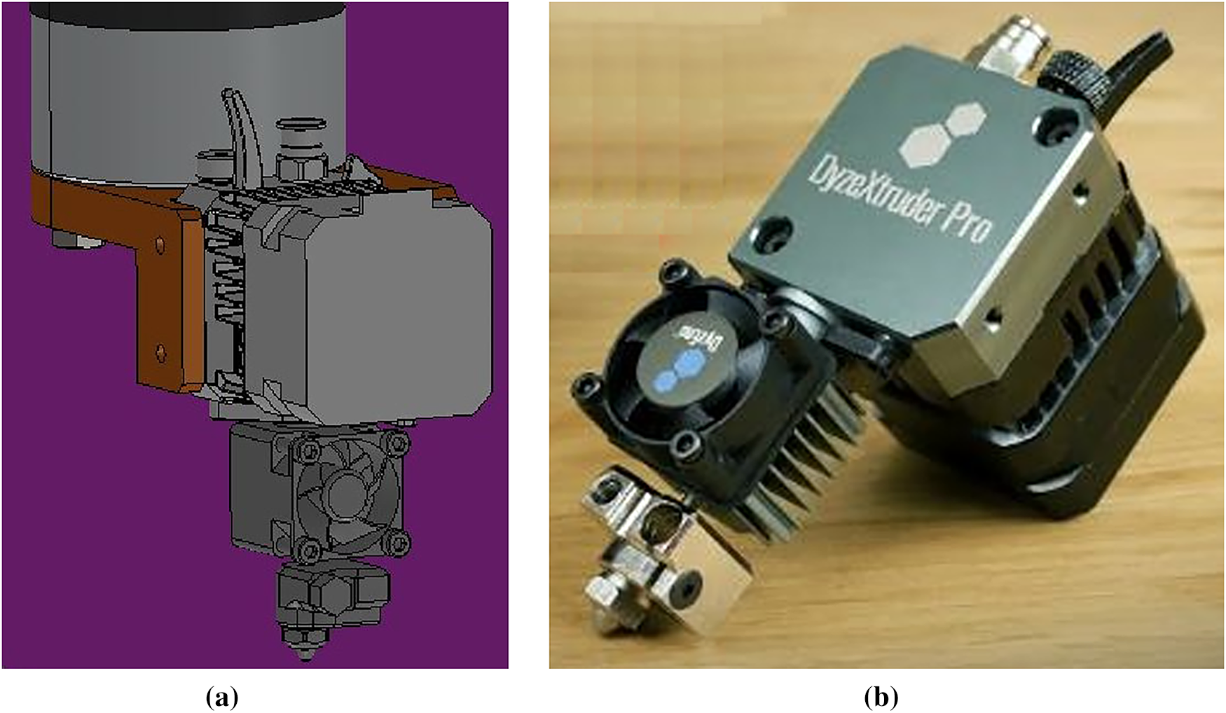
Figure 4. Extruder mounted on 3D robotic printing: (a) CAD designed stand; (b) experimental stand [3]
The programming of the cobot printing trajectory was performed in ROBODK software. The 3D printed samples were tested for compression and tensile. In own experiments, a Lloyd Instruments testing machine, model LRX plus, was used for tensile testing, running on NEXYGEN Plus software (Figure 5). The testing machine contains a library of pre-programmed test settings for performing fully automated tests, with respect to international standards.
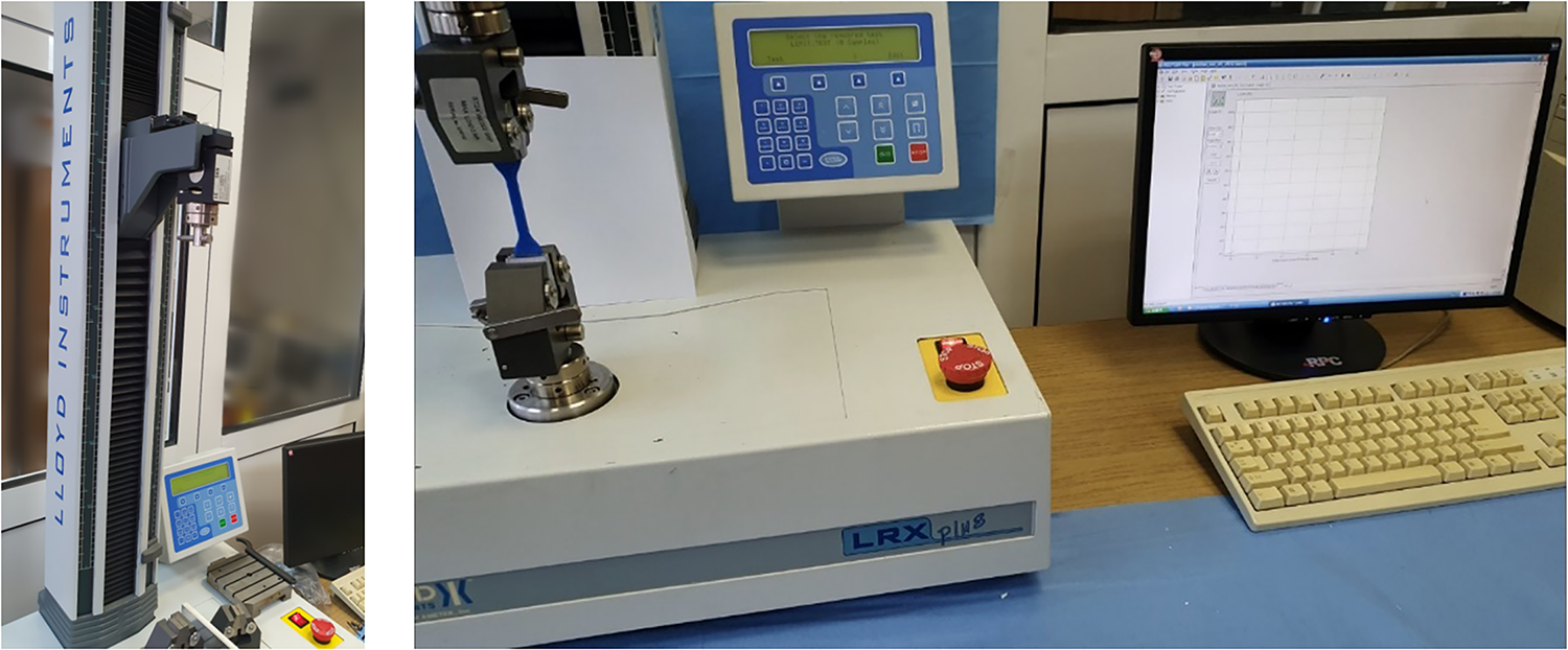
Figure 5. The 3D printed probe mounted on the testing machine [3]
2.2. Methodology used in obtaining the 3D printed probe
The main focus of our experiments is to determine the 3D printed probes’ mechanical properties for both planar 3D printing and nonconventional 3D printing and compare them. The 3D specimen used in the test is presented in Figure 6.
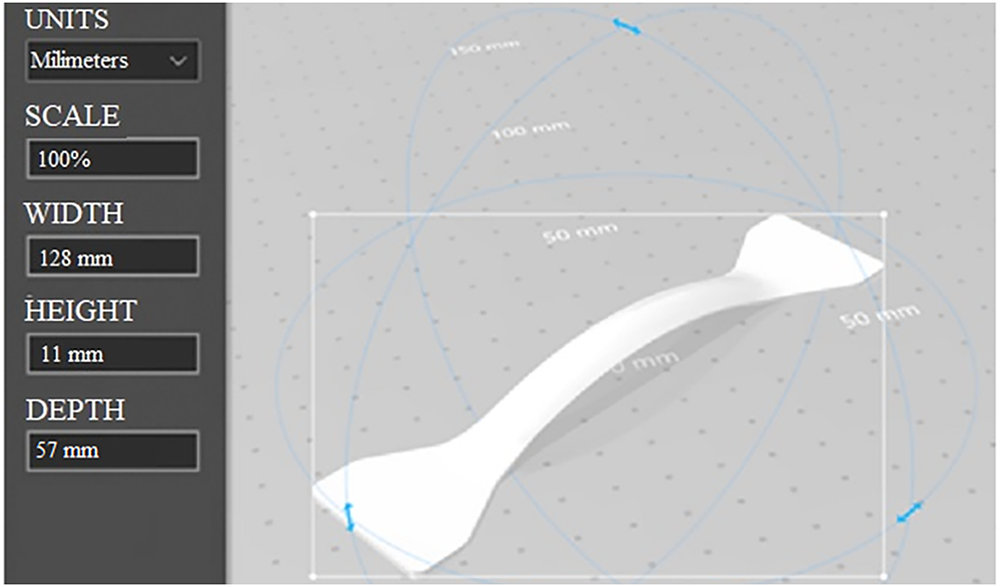
Figure 6. The 3D specimen used in the experimental tests
The specific work methodology used in our experiments is as follows:
1. 3D modelling of the test probe using spline-type curves.
2. Using the Cartesian G-Code format from the SLIC3R program and exporting to the ROBODK software. Overlaying the curves obtained with the help of the ROBODK software.
3. Adding the print flow for each obtained curve in the ROBODK software for the 7th axis corresponding to the extruder.
4. The compilation of the two programs into a single program. Importing to the UR3E robot from UNIVERSAL ROBOTS, Figure 7.
5. Performing a 3D test of parts by the robotic arm.
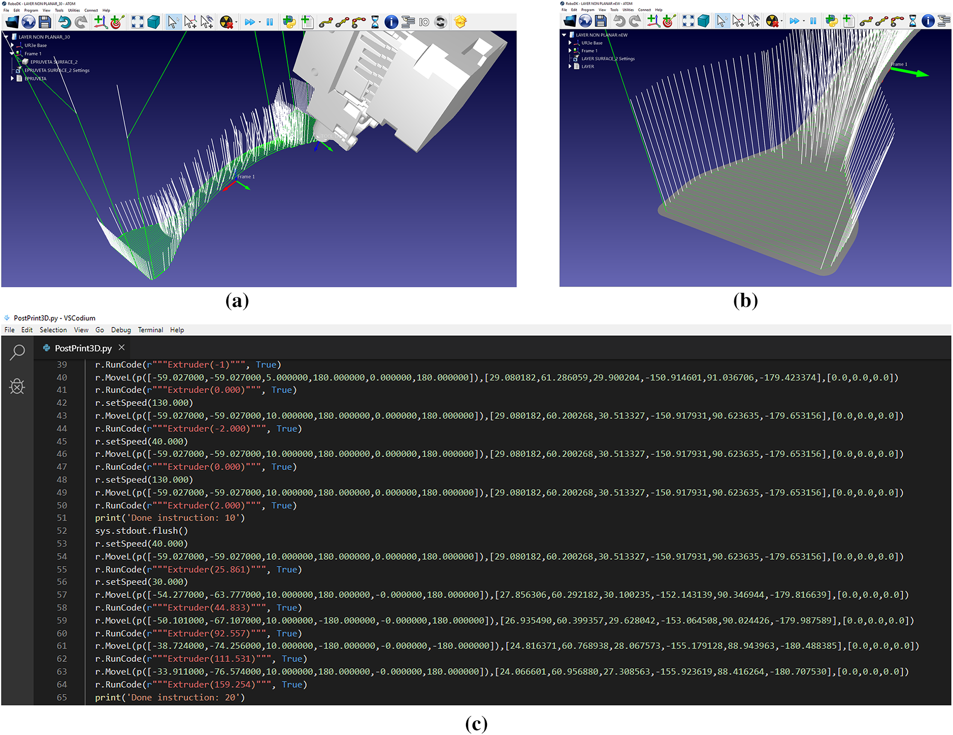
Figure 7. Simulation of the robot trajectory, (a) general view; (b) normal to surface; (c) G-code for UR3 robot (sequence)
The material selected for 3D printing is ONYX by Markforged, which is a composite material that includes carbon fiber. ONYX is a micro carbon fiber filled with nylon that yields accurate parts with a near flawless surface finish. Few materials have the versatility of Onyx, it offers high strength, toughness, and chemical resistance when printed alone, and can be reinforced with Continuous Fibers to yield aluminum-strength parts [14,15].
In order to certify the properties and the nature of the material used in 3D printing, we carried out an FTIR analysis (Fourier Transform Infrared Spectroscopy), which is an analytical technique used to identify organic, polymeric, and inorganic materials. The equipment used for material identification and characterization was a Bruker Vertex 70 FTIR spectrometer, equipped with a GateTM ATR diamond reflection unit. The wavelengths range from 4000 to 600 cm−1. The FTIR method uses infrared light in order to scan test samples and determine the chemical properties [16]. The results are presented in Figure 8.
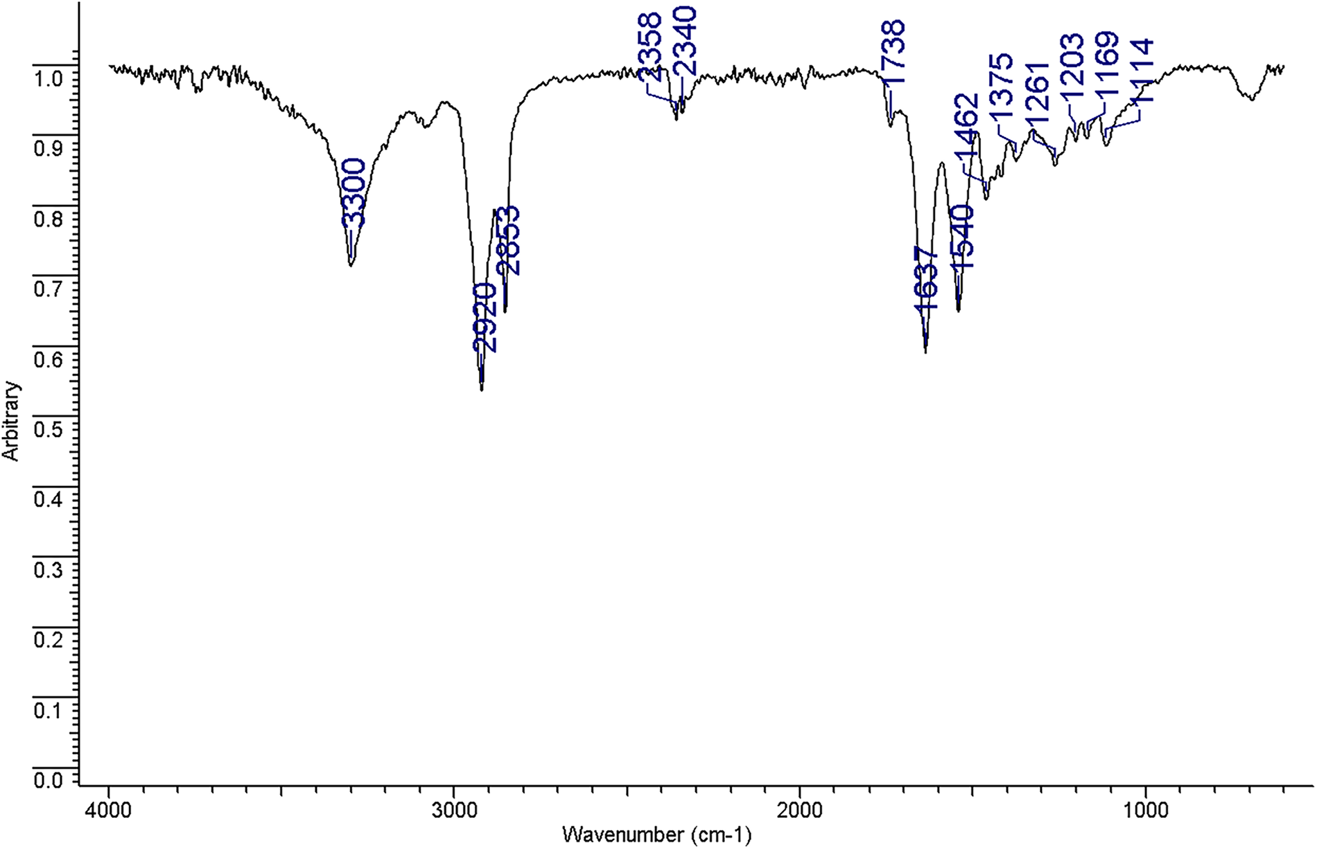
Figure 8. FTIR spectrum
At first glance, after performing spectrometry, the material in question appeared to be a Polyacrylamide—PAM. But this type of material cannot be used as a matrix for carbon fiber in 3D printing.
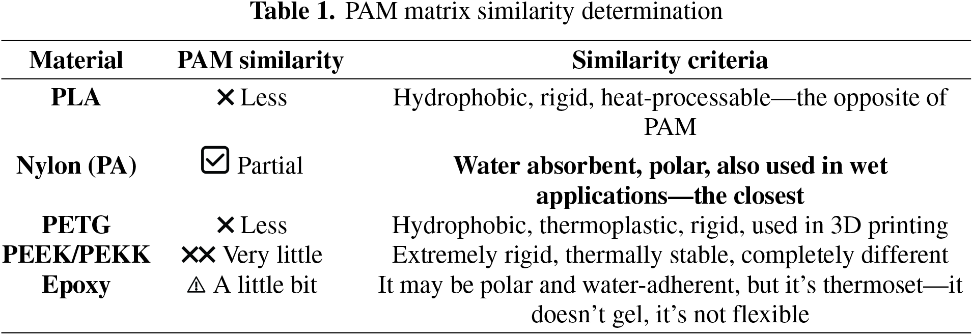
For this reason, the specialized literature was consulted and the existing matrices on the market were analyzed. It was thus determined that for matrices we have as a suitable alternative, the following thermoplastic or thermosetting polymer matrices: PLA (polylactide); Nylon (PA); PETG; PEEK/PEKK (for advanced applications); Epoxy (in lamination, not in classic 3D printing). The following criteria were considered for comparing materials used as carbon fiber matrices: Hydrophilicity (water absorption); Flexibility or gelation; Use in aqueous/wet solutions; Polar chemical structure; Low processing temperature.
The results are presented in Table 1.
Furthermore, the following presents the material properties extracted from the FTIR spectra for the mentioned materials. These spectra highlight the functional groups characteristic of each material, facilitating their comparison.
1. Polyacrylamide (PAM)
The FTIR spectrum of polyacrylamide shows the following characteristic bands:
• ~3300 cm−1: N–H stretching
• ~1650 cm−1: C=O amide (Amide I)
• ~1550 cm−1: N–H bending (Amide II)
• ~1200–1300 cm−1: C–N stretching
2. Nylon (PA)
The FTIR spectrum of nylon (polyamide) shows bands similar to those of PAM:
• ~3300 cm−1: N–H stretching
• ~1640 cm−1: C=O amide (Amide I)
• ~1550 cm−1: N–H bending (Amide II)
• ~1200 cm−1: C–N stretching
3. Polylactide (PLA)
The FTIR spectrum of PLA shows:
• ~1750 cm−1: C=O ester
• ~1183 cm−1 and ~1148 cm−1: C–O–C
• ~1074 cm−1: C–O–C
4. PETG
The FTIR spectrum of PETG (polyethylene terephthalate glycolate) shows:
• ~1715 cm−1: C=O ester
• ~1600 cm−1: Aryl C=C
• ~1500–1600 cm−1: Aryl C=C
• ~1300–1400 cm−1: C–C
5. PEEK (Polyetheretherketone)
The FTIR spectrum of PEEK shows:
• ~1600 cm−1: Aryl C=C
• ~1580 cm−1: Aryl C=C
• ~1500 cm−1: Aryl C=C
• ~1250 cm−1: C–O
• ~1150 cm−1: C–O
6. Epoxy
The FTIR spectrum of epoxy resins shows:
• ~915 cm−1: C–O–C epoxy
• ~1250 cm−1: C–O
• ~1600 cm−1: Aryl C=C
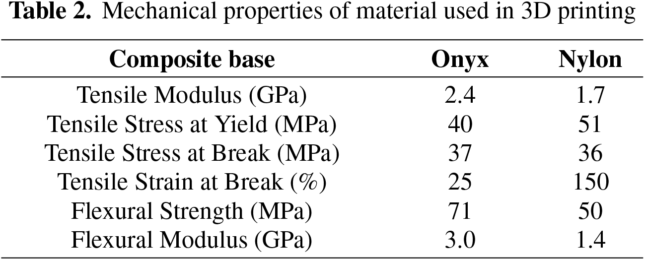
The analysis performed certifies that the matrices of material used in 3D printing is Nylon P6. The material was selected after consulting the scientific literature [12,13]. The closest type of material to the one analysed is Onyx. The mechanical properties of the material are presented in Table 2.
To compare the conventional/planar 3D and continuous 3D printing, several samples were printed using different printing parameters namely the nozzle diameter varied from 0.9 mm to 1.2 mm, the printing temperature from 250°C to 270°C. The test samples were subjected to UV radiation and to a humidity from 15% to 100%, as presented in Table 3, with notation.
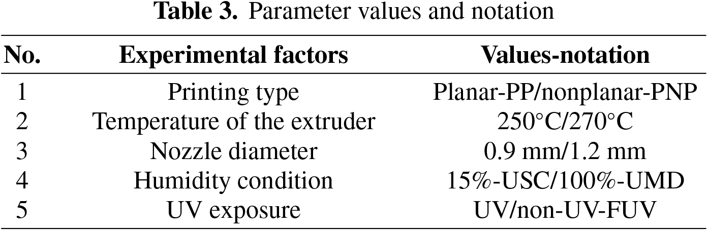
Five factors were considered in testing: the temperature of the extruder, printing type, nozzle diameter, humidity condition, and UV exposure (Figure 9). The results show that the type of printing nozzle diameter is of great importance in 3D printing. It must be emphasized that in all experiments we kept constant the wire feed speed and infill.
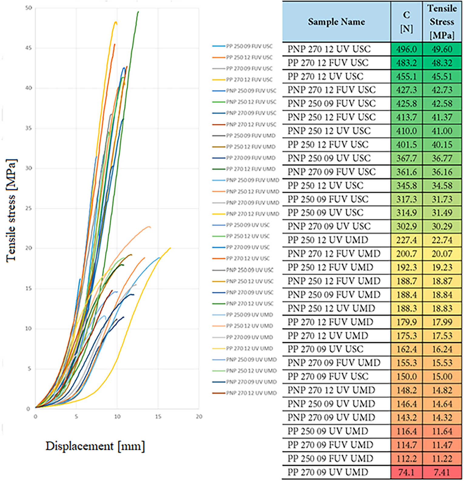
Figure 9. Maximum tension
Also, the results showed that another parameter that must be taken into account was the humidity. This is due to the material used in 3D printing, namely ONYX by Markforged, which has as a matrix nylon material P6. This material is a polar, water-absorbent polymer, and its mechanical behavior is influenced by humidity. The ONYX material has good resistance to UV. Also, the printing temperature and the nozzle diameter were important in obtaining a uniform deposed material sample and in controlling the material quantity. Based on the analysis of the results in Figure 9, it can be concluded that:
1. The most important influence on the physical-mechanical properties of the samples is given by humidity. This was expected because the matrix of the ONYX type material is nylon, which has a characteristic that its physical properties decrease with increasing humidity. In fact, this is very clearly observed, occupying the first place as an influence among the parameters, the samples have UMD in their notation.
2. Another parameter that influences the tensile strength of the sample is the nozzle diameter, so implicitly, the amount of material deposited. The deposition of a larger amount of continuous material leads to an increase in the tensile strength, considered as a positive aspect.
In Figure 10, the two types of tested parts, namely conventional/planar (upper image) and continuous/non-planar (lower image), breaks when a tension testing were performed.
3. The third parameter with decisive influence is the type of printing. It can be observed in Figure 9 that the nonplanar printed sample has 60% higher tensile stress at which the sample break compared to planar printed one. That can be explained considering the mechanism of the breaking process. In Figure 11 one can see that the nonplanar probe break in a transversal section while the planar printed sample breaks between the printed plane thus having a lower stress when breaks.
4. The fourth parameter is the melting temperature, which has an unexpected influence: the higher it is, the lower the tensile strength. The explanation consider that the material slightly changes its physical and mechanical properties at high temperatures.
5. Even if we expected that the material subjected to ultraviolet radiation would lose much of its characteristics, it is observed that this hypothesis is not met, the attack with ultraviolet rays having the least influence. The reasons that leads to a high UV resistance is again represented by the matrix of ONYX namely nylon.
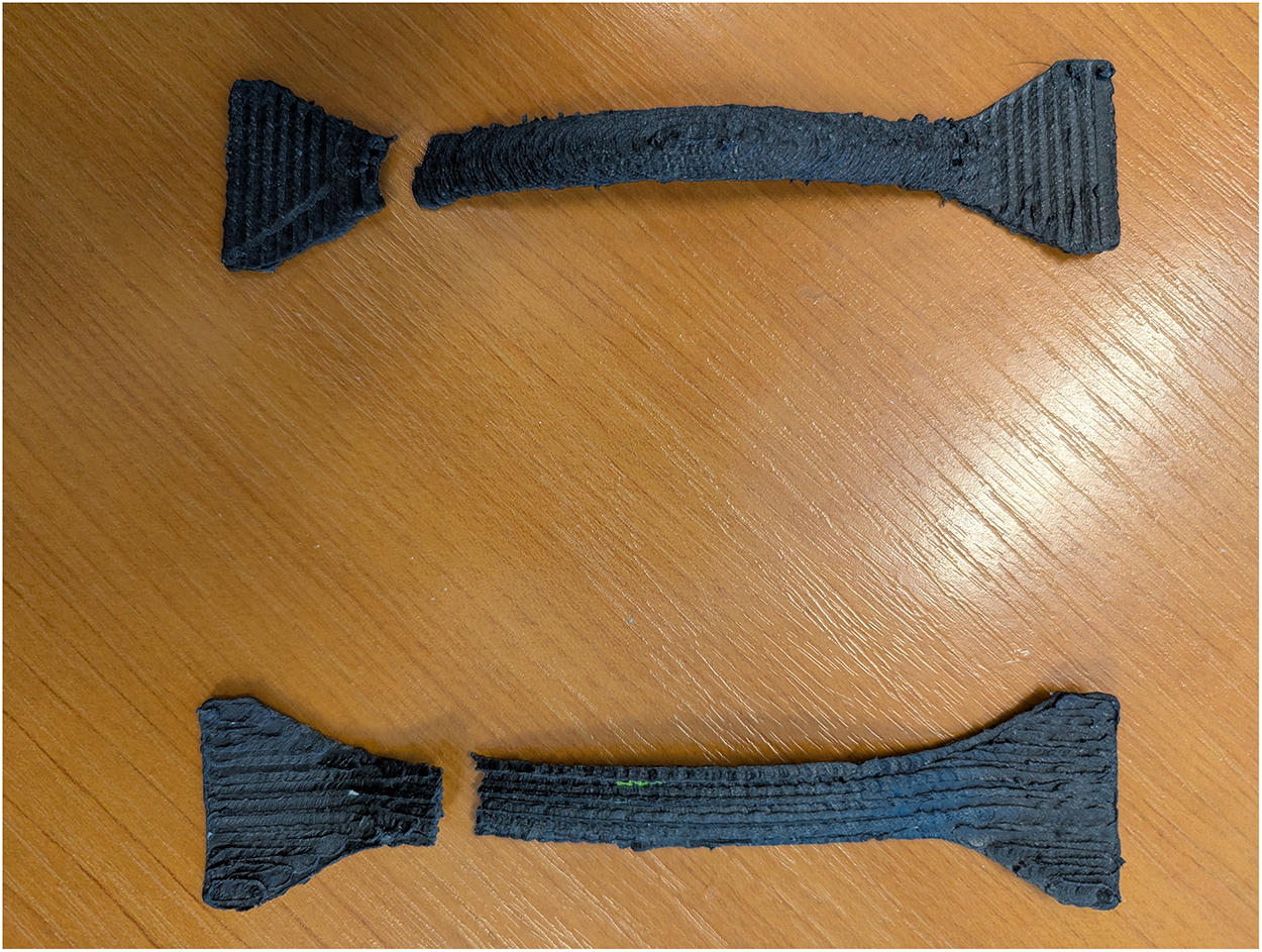
Figure 10. 3D printed samples: conventional/planar (upper image) and continuous/non-planar (lower image)
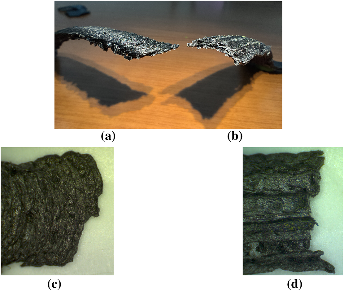
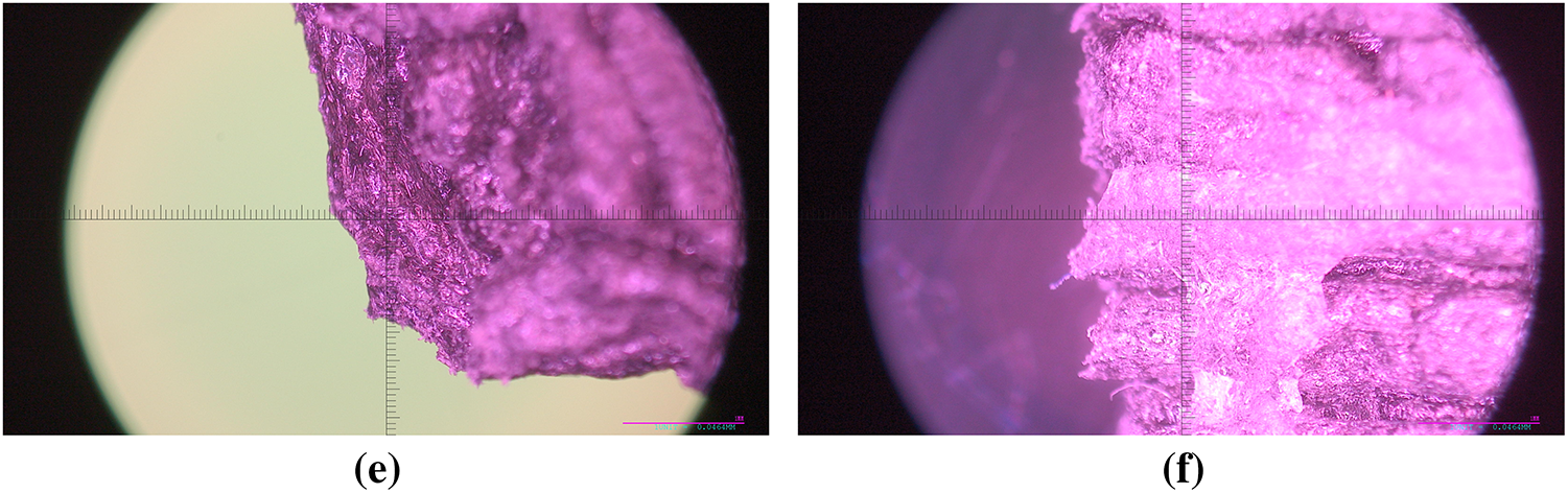
Figure 11. Increased images of the fracture zone: (a) planar; (b). nonplanar; (c) planar printing; (d). nonplanar printing; (e) planar printing (1 division–0.04 mm); (f) nonplanar printing (1 division–0.04 mm)
The load at which the samples in Figure 10 break is shown in Figure 12.
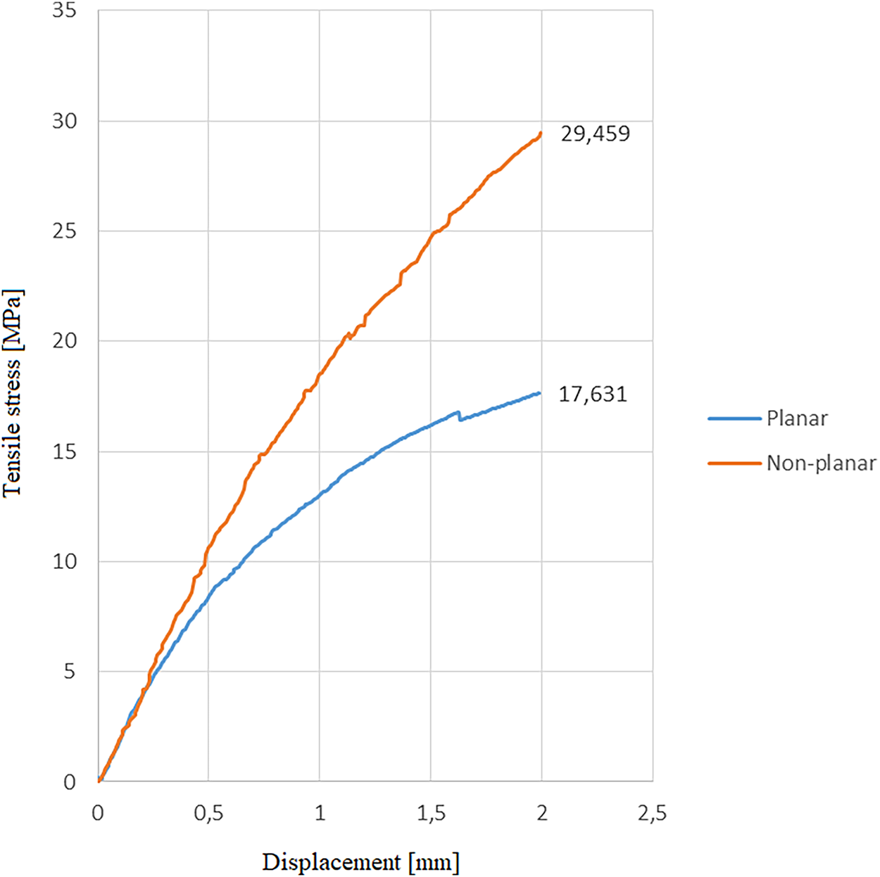
Figure 12. The maximum tensile stress at which the sample break
Experimental results revealed that the continuous 3D printed sample has attained a maximum load at sample fail of 29,459 N compared to 17,631 N for planar 3D printing resulting in a relative change in values of 67,08%, representing a significant increase over the initial value. Thus, the experiment confirms that the method employing the robotic arm and a continuous 3D printing trajectory is superior to the conventional planar 3D planar method.
The subject of this paper is to determine if the new 3D printing method that uses a robot arm and that can continuously deposit material in three-dimensional directions is feasible as a new 3D printing method. To prove the previous statement, several experiments were performed. One performed experiment compared the maximum tensile force at which the test samples broke. The samples were obtained from two types of conventional/planar and continuous/spatial printing methods. The obtained results indicate a stress value of about 68% higher for the continuously printed sample than the planar printing, which is related to better consistent fiber orientation along the load path without interruptions that can disturb alignment, reducing tensile and flexural strength, with fewer voids and geometric inconsistencies. Although there are still many things that need to be taken into account when printing, such as correlating the speed of movement of the robotic arm with the flow rate of the material in the extruder, creating a soft CAD interface—robotic arm, fulfilling the condition of keeping the extruder permanently perpendicular to the printing surface, studies conducted indicate a superiority of this 3D printing method over the conventional one. Future research will include software developments that will be necessary for smooth communication and control of both the extruder and the robot/cobot. When integrated with a feedback loop, the method can develop into a fully adaptive control strategy that enables real-time compensation for process variations. Furthermore, the use of a carbon fiber-type material in printing adds some benefits; however, there are some considerations that need to be followed. The choice of material must be closely related to the destination of the printed part and the working environment. It is noted that some materials are quite responsive to humidity or UV exposure. Although strong transferability of the experimental results has already been demonstrated, further steps are still required to ensure the scalability of robot-assisted manufacturing. Mainly, the system must be adapted to accommodate components with round geometries.
Acknowledgement: Not applicable.
Funding Statement: The authors received no specific funding for this study.
Author Contributions: The authors confirm contribution to the paper as follows: study conception and design: Fănică-Valeriu Hrib, Cătălin Gabriel Dumitraș; data collection: Florin Chifan, Emilian Păduraru; analysis and interpretation of results: Florin Daniel Eduțanu, Cătălin Fetecău; draft manuscript preparation: Mariana Ciorap. All authors reviewed and approved the final version of the manuscript.
Availability of Data and Materials: Data available on request from the authors.
Ethics Approval: Not applicable.
Conflicts of Interest: The authors declare no conflicts of interest.
How to Cite this Article
References
- Ionesi SD, Ciobanu L, Dumitras C, Avadanei M, Dulgheriu I, Ionescu I, et al. FEM analysis of textile reinforced composite materials impact behavior. Materials. 2021;14(23):7380. doi:10.3390/ma14237380; 34885535 DOI
- Shi H, Zhou P, Li J, Liu C, Wang L. Functional gradient metallic biomaterials: techniques, current scenery, and future prospects in the biomedical field. Front Bioeng Biotechnol. 2021;8:616845. doi:10.3389/fbioe.2020.616845; 33553121 DOI
- Hrib VF, Chifan Fl, Dumitraș CG. Comparative study between conventional and robotic methods in 3D printing. Bul Institutului Politeh Din Iaşi. 2023;69(4):79–91. doi:10.2478/bipcm-2023-0037. DOI
- Chitariu DF, Paduraru E, Dogan G, Ilhan M, Negoescu F, Dumitras CG, et al. Experimental research on behavior of 3D printed gripper soft jaws. Mater Plast. 2020;57(4):366–75. doi:10.37358/Mat.Plast.1964. DOI
- Bhatt PM, Kabir AM, Malhan RK, Shah B, Shembekar AV, Yoon YJ, et al. A robotic cell for multi-resolution additive manufacturing. In: Proceedings of the 2019 International Conference on Robotics and Automation (ICRA); 2019 May 20–24; Montreal, QC, Canada. p. 2800–7. doi:10.1109/icra.2019.8793730. DOI
- Stanciu NV, Rosculet RT, Fetecau C, Tapu C. Forensic facial reconstruction using 3D printing. Mater Plast. 2021;57(4):248–57. doi:10.37358/mp.20.4.5424. DOI
- Safeea M, Bearee R, Neto P. An integrated framework for collaborative robot-assisted additive manufacturing. J Manuf Process. 2022;81(3):406–13. doi:10.1016/j.jmapro.2022.06.067. DOI
- Jiang J, Newman ST, Zhong RY. A review of multiple degrees of freedom for additive manufacturing machines. Int J Comput Integr Manuf. 2021;34(2):195–211. doi:10.1080/0951192X.2020.1858510. DOI
- Pollák M, Kočiško M. Design and implementation of 3D printing using a universal printing system on the robot arm UR5. TEM J. 2021;10(4):1895–9. doi:10.18421/tem104-53. DOI
- Pollák M, Kočiško M, Grozav SD, Ceclan V, Bogdan AD. Suitability of UR5 robot for robotic 3D printing. Appl Sci. 2024;14(21):9845. doi:10.3390/app14219845. DOI
- Chitariu DF, Agache TM, Dumitras CG, Horodincă M, Edutanu FD, Chiriac GG. Experimental research on positioning accuracy of educational robots. Acta Tech Napoc Ser Appl Math Mech Eng. 2024;67(2):595–604.
- Abadie MJ, Manole I, Fetecau C. Photosensitive formulation for additive manufacturing-3D printing. Mater Plast. 2020;57(1):141–52. doi:10.37358/Mat.Plast.1964. DOI
- Stan F, Stanciu NV, Fetecau C. On the 3D printability of multi-walled carbon nanotube/high density polyethylene composites. In: Proceedings of the 14th International Manufacturing Science and Engineering Conference; 2019 Jun 10–14; Erie, PA, USA. doi:10.1115/MSEC2019-2776. DOI
- Rădulescu B, Mihalache AM, Păduraru E, Hriţuc A, Rădulescu MC, Slătineanu L, et al. Tensile behavior of chain links made of polymeric materials manufactured by 3D printing. Polymers. 2023;15(15):3178. doi:10.3390/polym15153178; 37571070 DOI
- Markforged. Composites [Internet]. [cited 2026 Apr 1]. Available from: https://s3.amazonaws.com/mf.product.doc.images/Datasheets/Material+Datasheets/CompositesMaterialDatasheet.pdf.
- Gong Y, Chen X, Wu W. Application of fourier transform infrared (FTIR) spectroscopy in sample preparation: material characterization and mechanism investigation. Adv Sample Prep. 2024;11:100122. doi:10.1016/j.sampre.2024.100122. DOI