Abstract
Keywords: Graphene; nanocomposite; starch biopolymer; arrowroot; bionanocomposites
In the pursuit of environmentally sustainable materials, scholars have increasingly focused on biocomposites as viable substitutes for conventional synthetic polymers [1]. The primary constituents of the material class referred to as biocomposites consist of a biodegradable polymer matrix and one or more fillers [2]. When these components are combined, the mechanical properties improve. Natural fibers are increasingly being used in place of synthetic fibers when making biocomposites. Examples of these fibers include flax, hemp, sisal, and others [3]. The use of these fibers will bring higher sustainability.
The arrowroot plant (Maranta arundinacea) is essential to the production of biodegradable goods like biocomposites. The primary source of arrowroot’s fiber and starch is the rhizome. It has tuberous rhizomes and lengthy, fibrous roots [4]. The rhizome of arrowroot has a high starch content. It is well known that the extracted starch digests quickly and has good gelling qualities. Because of its high amylose content of 35.20%, it can be used to produce films [5]. Due to its versatility as a hydrocolloid, thickening and gelling agent, encapsulating and coating agent, and as a component of economically friendly electronic products such as sensors, this starch has a great deal of potential to replace ordinary starch [6].
A single sheet of carbon atoms organized in a hexagonal pattern is called graphene [7]. It is the thinnest substance in the world, with a thickness of just 0.334 nm [8]. They have an enormous specific surface area of 2600 m2/g, a high electron mobility of 200,000 cm2/Vs, an enhanced thermal conductivity of 3000–5000 Wm/K, an extreme optical transparency of 97.4%, remarkable mechanical strength, and a Young’s modulus of 1TPa are just a few of their unique properties [9]. Industrially available graphene nanoplatelets are a combination of graphene and graphite. Because of their planar shape, low weight, high aspect ratio, electrical conductivity, affordability, and mechanical durability, these nanoparticles are appealing [10]. Numerous technical fields have already made use of graphene nanoplatelets (GNP) [11]. The tribology, mechanical, biological, gas barrier, flame retardant, and heat conduction properties of GNPs-based materials are enhanced. Moreover, GNPs could change plastic into an electrical conductor and a conformable electronic material [12].
Biopolymer composites are under consideration to replace conventional polymers, which are widely used for various applications that require good physical, morphological, and mechanical properties, which are not achieved in the case of GNP and arrowroot starch (AS) biocomposite [13]. This replacement consideration is due to the polymer environmental issues and hazards during the manufacturing process, as it produces chemicals that can be harmful to humans [14]. The high amylose content (between 16% and 27%) of AS makes it a suitable polymeric material to produce biodegradable films [15]. Better mechanical and physical qualities can be achieved by producing films with a higher amylose concentration in the starch [16]. Thus, it is crucial to determine the properties of biopolymer composites such as GNP and AS biocomposites, as they can be a potential replacement.
Although the inherent nature of the arrowroot-derived thermoplastic starch is biodegradable and renewable, a rigorous analysis of its degradation behaviour, recyclability, and life-cycle performance is needed to support the arguments of sustainability [17]. The incorporation of graphene nanoplatelets (GNPs) can significantly change the environmental footprint of the composite through changing the biodegradation rates, microstructural disintegration mechanisms, and end-of-life behaviour [18]. A case in point, carbon nanofillers of high aspect ratio decrease water permeability and accessibility to the microbes, and thus, they may slow down hydrolytic and enzymatic degradation of the starch structure [19]. Besides, importances like mechanical stability of reprocessing and maintenance of filler across repeated processing cycles should be analyzed to determine the circularity of the materials. An analysis of environmental sustainability will be more realistic, taking into consideration all the cycles of life, such as the sourcing of raw materials, fabrication energy requirements, duration of operations, and disposal channels [20]. Therefore, critical analysis of degradation, recyclability potential, and life implications is required to scientifically validate graphene-reinforced arrowroot starch films to use in the flex route of electronics, besides just citing their bio-based origin.
Better mechanical and working capability of distinguished composites of graphene nanoplatelet-reinforced arrowroot starch is not due to increased dispersion at all but must be explained through the prism of a mechanistic approach only [21]. At low filler loadings, single GNPs mainly behave as stress concentrators, but with a further increase in the concentration, a continuous conductive and load-bearing network will develop, approaching both the electrical and mechanical percolation limits [22]. This percolated network helps in carrying out effective electron transport pathways and redistribution of stresses across the matrix of the composite. Efficiency in reinforcing is further controlled in interfacial stress transfer between GNPs and the thermoplastic starch matrix. The transfer of the load depends on the interfacial adhesion, hydrogen-bonding between hydroxyl groups of starch and oxygen-containing groups of the graphene surfaces, and an important threshold of filler interactions with the matrix, which has an alleviating effect on the pull-out and the slippage. The balance between filler agglomeration and network structure determines the switch in behavior between reinforcement-dominated and defect-dominated behavior [23]. Hence, explanation of the percolation process, interfacial bonding, and interaction energy explains the structure-property relations, which are a unique characteristic of the graphene-reinforced arrowroot starch films.
One of the most common applications of graphene nanoplatelets is due to their high electrical conductivity, large specific surface area, mechanical strength, and chemicals. However, other graphene-based nanomaterials such as graphene oxide (GO), reduced graphene oxide (rGO), and graphene quantum dots (GQDs) have different physicochemical properties that are especially relevant in flexible electronics and nanosensor technology [24]. GO has a lot of oxygen functional groups, such that the groups improve the dispersibility in hydrophilic biopolymer matrices and strong interfacial interactions with hydrogen bonds. When a sp 2 carbon network is partially restored, rGO gains an increase in electrical conductivity without losing functional groups that enhance its compatibility with matrices, thus making it a strain sensor, piezoelectric transmitting material, and a flexible conduction film. Quantum confinement and edge-state motor belonging to the category of GQDs, these materials exhibit tunable photoluminescence, large surface reactivity, and greatly highly efficient with biocompatibility, which are beneficial to optical sensing and bioelectronic technologies [25]. The use of hybrid, more so, GNPs in combination with GO, rGO, or GQDs allows further optimization of electrical, mechanical, and sensing functionality by means of synergistic optimization of conductivity, functionality, and dispersion stability [26]. Thus, the necessary accentuation of the peculiarities and nano-sensor use of these graphene derivatives emphasizes the novelty and the topicality of the graphene-based arrowroot thermoplastic starch composites to further electronic appliances of the next generation [27].
This research study effectively fills the essential void in the creation of material systems that characterize sustainable, high-performance materials in flexible electronics, namely, the study of the characteristics of a new GNP and AS biocomposite. Whereas earlier research has already covered the topic of biocomposites, the morphological, physical, and mechanical characteristics of this combination have not been thoroughly covered. We show that the tensile strength and Young’s modulus of the biocomposite increase when the GNPs are introduced, with an optimal loading of 5% GNP producing the highest tensile strength and Young’s modulus, turning the material tougher and harder. These mechanical findings were supported by the Field Emission Scanning Electron Microscopy (FESEM) analysis, whereby at the higher concentration (10%), GNP agglomeration forms voids that eventually destroy the integrity of the material. These findings bridge an important gap in knowledge as they enable a clear direction to be taken in the future to develop safer, quality, and eco-friendly sensors and other electronic elements. The research points out that through the proper regulation of the concentration of GNP, it can be possible to adjust the physical characteristics of the biocomposite to suit the exacting needs of the next generation of electronic devices.
Arrowroot rhizomes were obtained from a supplier through a local store. The glycerol and sorbitol plasticizer, which has a purity value of 99.5%, is provided by Evergreen Engineering & Resources, Semenyih, Selangor, Malaysia. The solvent for preparing filmgenic solutions was distilled water. The GNP is procured from GO Solution Sdn. Bhd, Kuala Lumpur, Malaysia. Figure 1 shows the flow chart of the methodology process for this research work.
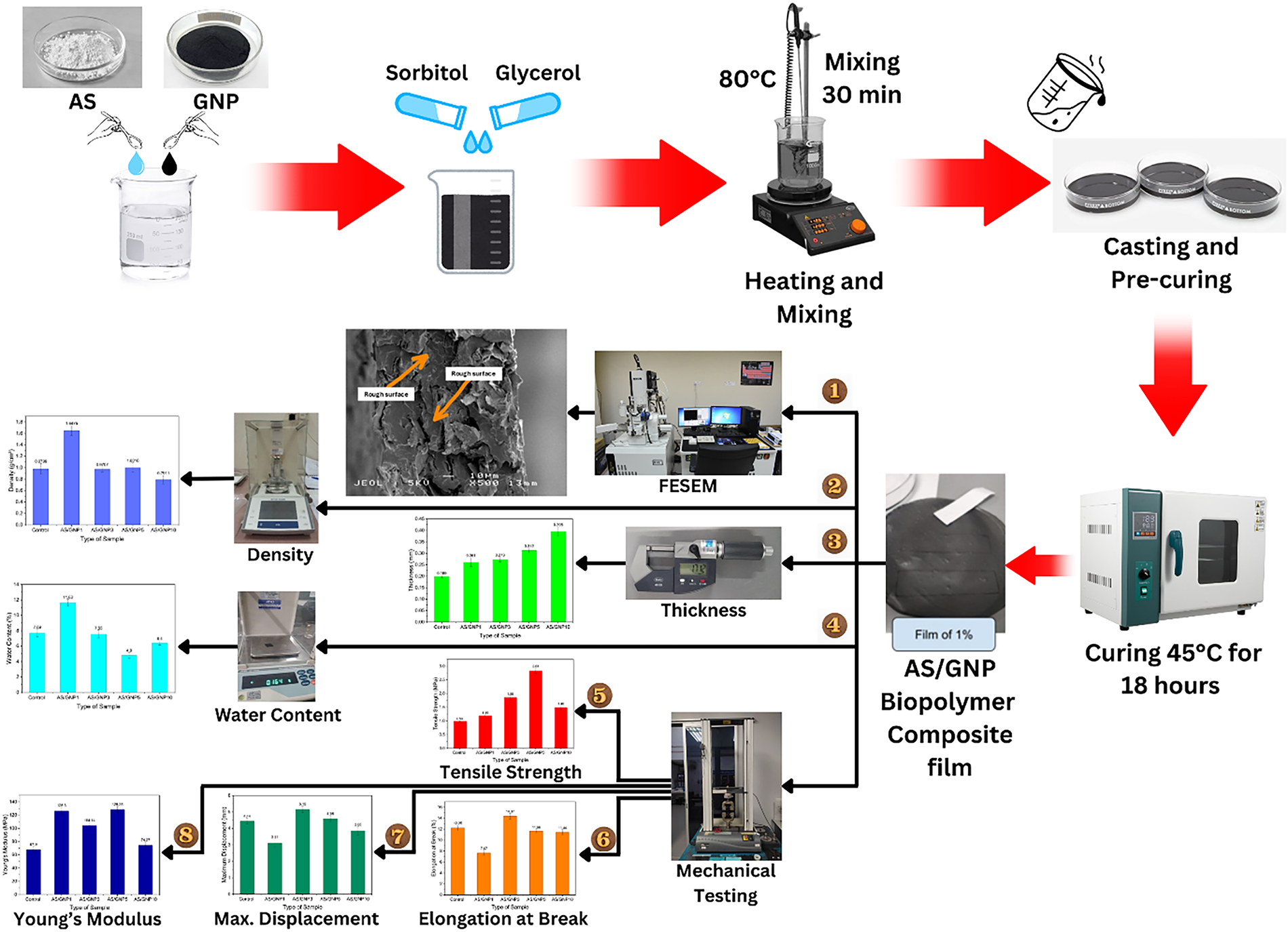
Figure 1. Flow chart of the methodology process
The extraction of AS involved a conscientious process to obtain high-quality AS. With certain modifications, AS was extracted using a technique described by Nogueira et al. [28]. The rhizomes of arrowroot were chosen, peeled, cleaned with pipetted water, sliced, and left in a solution of potassium metabisulfite (0.03%, m/m) for 15 min. After that, it was crushed for five minutes in a high-speed stainless steel industrial blender (Toshiba BL-70PR1NMY 2.0L Blender) using distilled water in the ratio of 1:2 (m/m) of arrowroot to water, until a homogenous mass was achieved. A double cotton cloth filter was used to filter the obtained material. Three rounds of mass washing with distilled water were required to completely remove the starch and separate the fibers. Following around 12 h of starch sedimentation, the water was manually separated using a flow mechanism. Figure 2 shows the flow chart of the AS extraction.
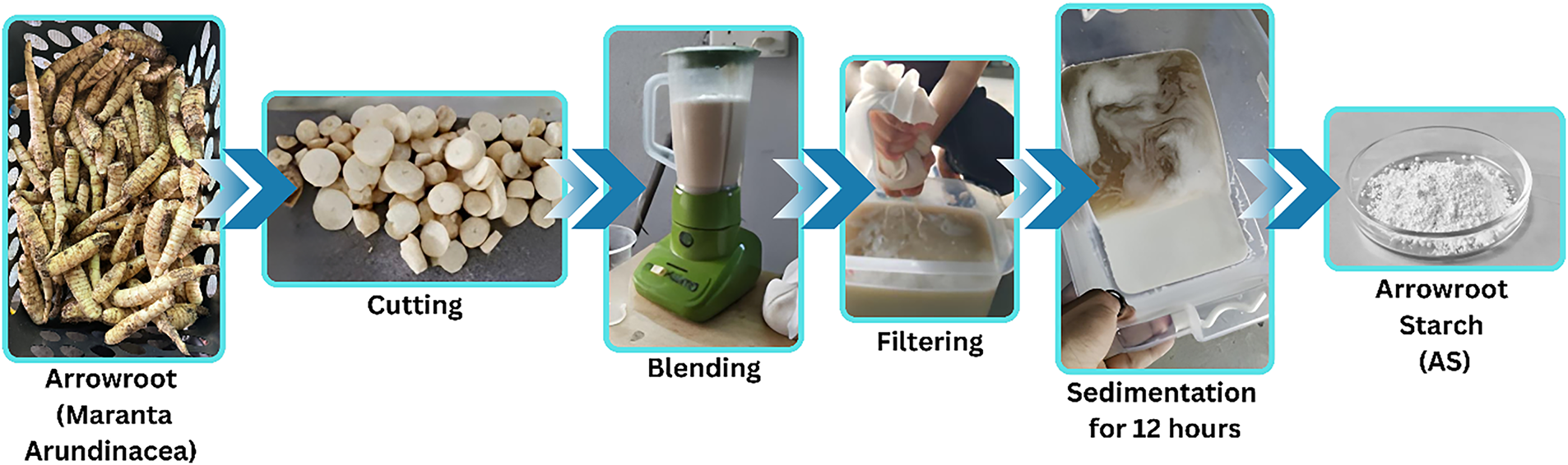
Figure 2. The flow chart of AS extraction
The conventional solution casting method was used to prepare arrowroot-based films. The process of dissolving a substance or polymer in an appropriate solvent and then casting or spreading the solution onto a substrate is known as solution casting, and it is a technique used to make thin films or coatings. This method is commonly employed in the fabrication of polymer films, composite materials, or thin coatings. Starch was dissolved in distilled water, and the mixture is heated to 85°C in a thermostatic bath while stirring continuously for about five minutes. The starch solution was then homogenized after glycerol and sorbitol of combined 30% were added in a ratio equal to 1:1.
Boonphayak et al. reported that the glycerol sorbitol mixture produced a biofilm with desirable characteristics to be used in packaging such as significantly decreased solubility and good elongation performance [29]. These are the qualities required in the development of good packaging materials. The findings explain the synergistic activity of adding the glycerol sorbitol mixture at the concentration of 30 wt-based (1:1 ratio) which gave them increased water resistance and reduced solubility, especially when strengthened with an AS/GNP composite film [29].
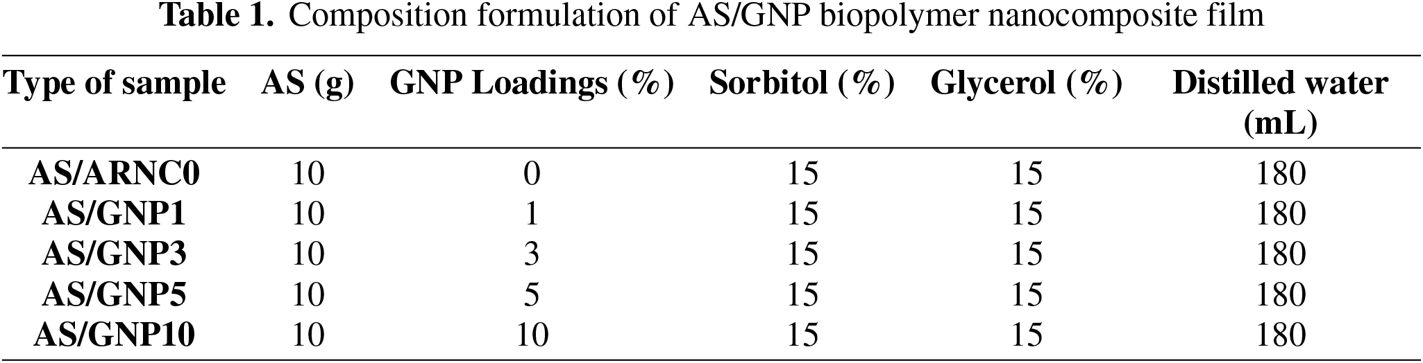
Then, 1, 3, 5 and 10% of GNP is added into four different solutions. There are 4 samples that contain the GNP solution and one constant variable which does not contain GNP. The resultant solutions were poured into 14 cm-diameter petri dish plates in aliquots of 53.85 g each. After 12 h at room temperature (25 ± 5°C), the films were dried [30]. The films were dried and then conditioned at 45°C for 18 h before being characterized. The temperatures of 45°C and 15 h were chosen as the optimum temperature due to the reported result using high temperatures (Ilyas et al. and Sanyang et al.). High temperatures might cause thermal degradation or damage on the nanocomposite film; therefore, the use of high temperatures was avoided to prevent loss of material integrity [31,32]. Figure 3 shows the film forming process while Table 1 shows the composition formulation of AS reinforced GNP biopolymer composite film.
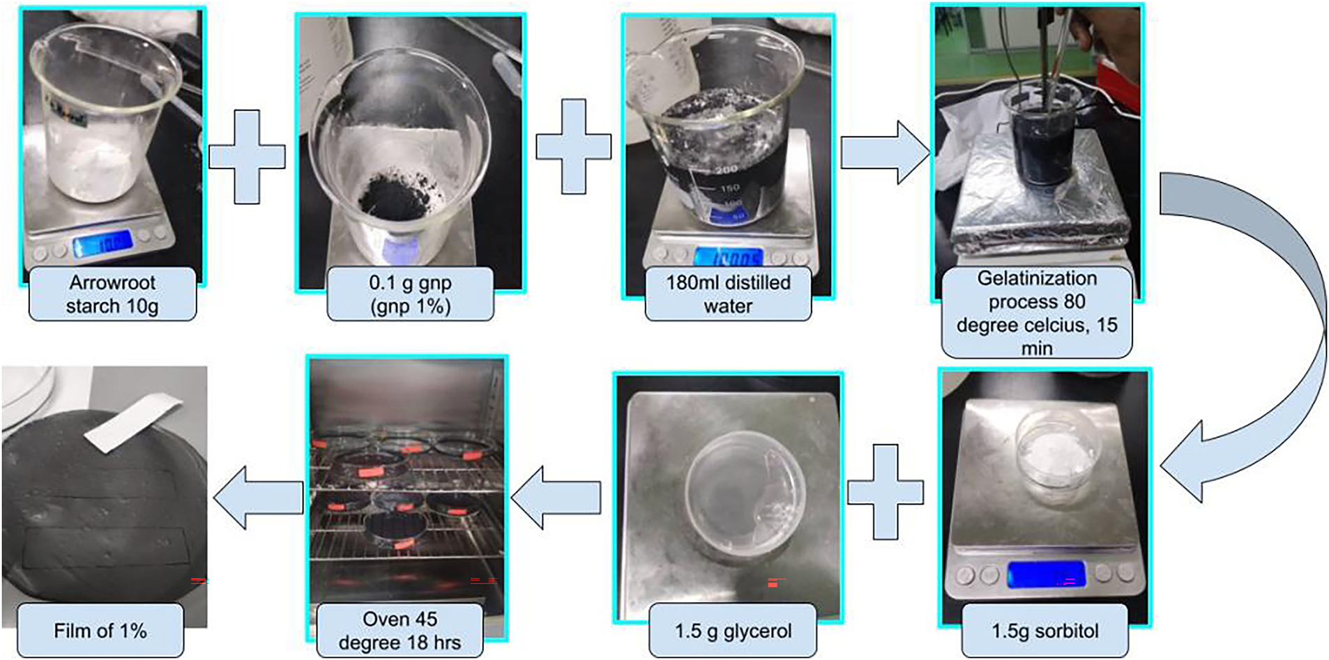
Figure 3. The flow chart of AS reinforced GNP biocomposite film preparation
The physical properties of the AS/GNP biocomposite film are influenced by its thickness, which is a crucial parameter. A precise assessment of the film’s thickness is necessary to guarantee consistency and uniformity across a range of uses. A thorough grasp of thickness helps regulate the weight and flexibility of the material, especially in applications like packaging where adhering to strict thickness specifications is essential to preserving product integrity. To measure the thickness of the film samples with an accuracy of 0.001 mm, A digital micrometer can be used. This method follows ASTM method F2251 [33].
The measurement of the density of the composites was done on a densimeter (XS205, Mettler-Toledo (M) Sdn Bhd.) according to the ASTM standard D792 [34]. The size of the sample was 20 × 20 mm and ethanol was used as the immersion liquid here. Each of the three measurements was moved through an equation to determine the density (ρ) by using Eq. (1).
(1)
where the m, mass was measured in grams (g), and the v, volume was calculated by multiplying the film’s area by its thickness. The thickness of the biopolymer composite film was measured using a micrometer (Mitutoyo-CO, Kawasaki, Japan) having precision of 0.001 mm. Each film was also measured in three replications and later calculated according to the ASTM Method F2251 [35]. The average value resulting from the measurements of the film provided the actual film thickness.
The water content of the AS/GNP biocomposites is another significant aspect influencing their performance in various applications. This employs the ASTM D664-07 methodology. All samples were first weighed (Mi) and then dried at 105°C for 24 h. Afterward, they were weighed again (Mf). Eq. (2) shows the equation of Water Content, WC (%) [33].
(2)
Tensile testing was done on the films to ascertain their mechanical characteristics with ASTM D882-02 standard. The films of all GNP loadings and controls must be cut into 70 mm × 10 mm and fastened between the machine’s clamps. The testing is done on a 5 kN Instron 3366 tensile machine with gauge length and crosshead speeds of 30 mm and 2 mm/min. A total of 5 samples were taken for each variation of films and the mean value is taken [36].
2.3.5 Field emission scanning electron microscope (FESEM)
A field emission scanning electron microscope (FEI Nova NanoSEM 230) was used to observe the morphology of the biopolymer composite films. The samples were coated with thin layer of gold through argon plasma sputter coating in order to avoid surface charging [37]. FESEM analysis then was conducted at accelerating voltage of 3 kV.
2.4. Differential scanning calorimetry (DSC)
Differential scanning calorimetry of the AS/GNP composite materials were found with the help of a Mettler Toledo (Malaysia) differential scanning calorimetry (DSC) device. The temperature of the specimens was raised during the examination by heating them at a steady rate of 10°C between 25 and 300°C. The experiment was conducted in the condition of 40 mL/min nitrogen flowing.
The fabrication of the film was done to fit the four-probes test apparatus as per the dimensions needed. A Keithly 2400 Source SMU that was used in DC mode (Tektronix, Beaverton, United States) and a 4-point probe MST-2000A Four-Point Probe System (MSTECH Co., Ltd., Republic of Korea) were used to measure the V-I properties of the AS/GNP nanocomposite film.
The bar chart in Figure 4 shows the thickness of the different composite film samples, which include a control sample and arrowroot starch reinforced with increasing loadings of GNP of 1%, 3%, 5% and 10%. An apparent trend of change is observed in which GNP addition to the starch matrix results in a gradual increase in the film thickness compared to the control sample [38].
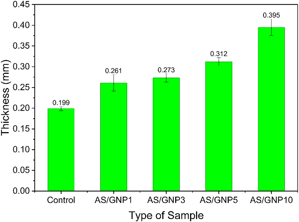
Figure 4. Graph of thickness with different loadings of the GNP film sample
The control film records the lowest thickness of 0.199 mm, therefore, forming a relative benchmark. When 1% GNP (AS/GNP1) is incorporated, the thickness value significantly increases to 0.261 mm, which suggests that the addition of nanofillers contributes to film formation and potentially films can be improved through molecular packing. This is followed by increases in AS/GNP3 and AS/GNP5, reaching a thickness of 0.273 and 0.312 mm, respectively. These data indicate that the increase in the concentration of the GNP contributes to the densification of the film and the strengthening of the structure [39].
The highest reading of the thickness of AS/GNP10 is 0.395 mm, and it nearly doubles that of the control samples. The analysed significant growth opportunities indicate that high GNP loadings appear to cause reinforcement of the interfaces and facilitate the structuring and consolidation of the film [40]. However, the same phenomenon could also refer to greater filler aggregation, thus influencing the structure of the film [41]. Overall, the empirical data reveal that the addition of graphene nanoparticles (GNPs) produced a direct effect on the film, thus indicating a positive correlation between the concentration of nanoplatelets and the dimensional features of the formed film [42].
Figure 5 shows the density of the AS/GNP composite films, which indicates there is a pronounced correlation between density and the loading level of GNPs. The density of the unmodified control sample is 1.175 g/cm3. Denser incorporation of 1% GNP (AS/GNP1) causes a significant increase in density to 1.4475 g/cm3, which is the highest value of all the specimens. This sharp improvement shows that a small addition of GNP can enhance the packing ability of the starch matrix, presumably due to enhanced dispersion and strong interfacial behavior between AS and GNP. This densification effect is achievable by the naturally strong intrinsic density of graphene, which leads to the corresponding increase in the compactness of the matrix [43].
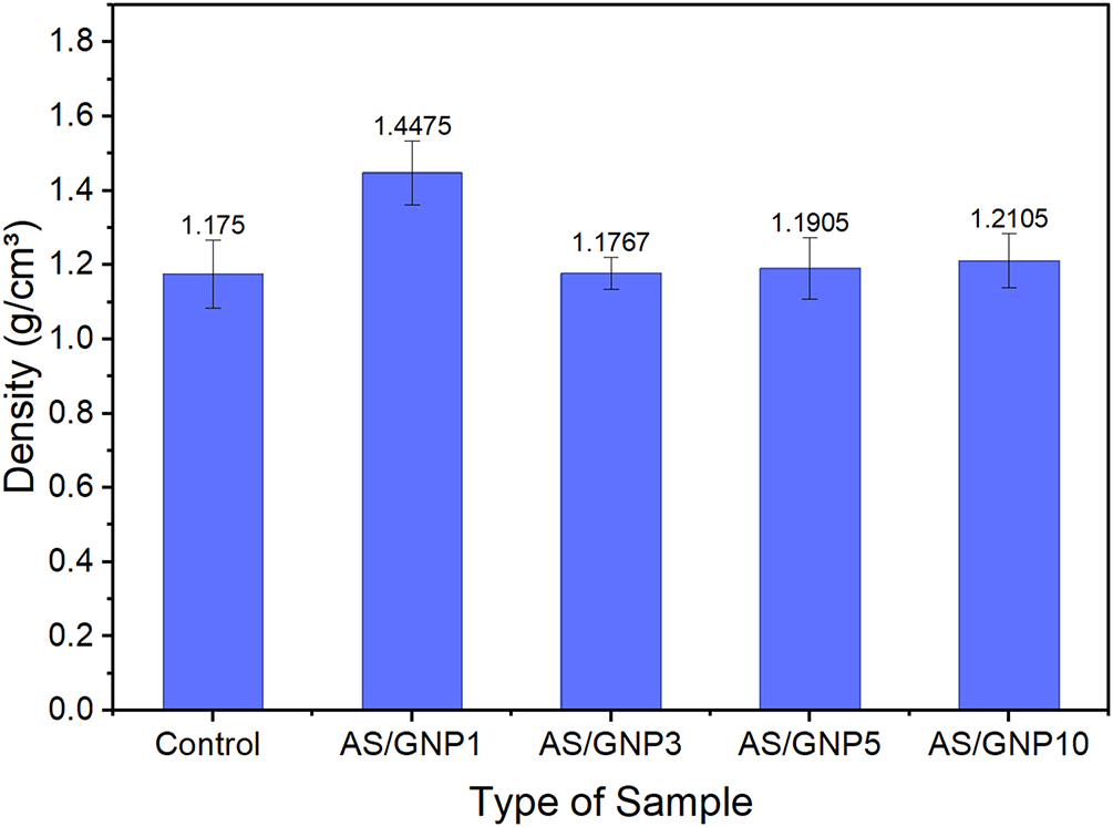
Figure 5. Graph of density with different loadings of the GNP film sample
When graphene nanoplatelets (GNP) are added to the aqueous starch (AS) matrix, the addition of only the first batch of the filler causes increased density, but threshold changes are minimal, which indicates a possible filler agglomeration and dispersion limitation at higher loading [44].
On the other hand, increasing the GNP content up to 3%, 5%, and 10% reduces the density to 1.1767, 1.1905, and 1.2105 g/cm3, respectively. Such values are also close to the control and significantly less than those of AS/GNP1. The trend suggests that loading beyond 1% reduces GNP dispersion homogeneity, which encourages agglomeration. Aggregated GNP may cause micro-voids or reduce effective packing into the matrix, thereby compensating the expected density increase of a high-density filler. The small incremental change from 3% to 10% is because of partial filler contribution, but the resulting effect is not as high as in the case of 1% loading [45].
The recorded standard deviations are moderate, especially for AS/GNP1 and AS/GNP10, which can be explained by heterogeneity in the filler distribution. Overall, the information demonstrates that GNP loading in the AS matrix is optimized at 1%, while higher loading creates structural anomalies limiting additional increases in density. This behavior is consistent with known nanofiller systems, where there is an optimum filler concentration above which agglomeration prevails in the composite structure.
The Figure 6 bar chart illustrates the water content (%) of AS/GNP biopolymer nanocomposite films with varying GNP loadings compared to the control. The control sample recorded a water content of 7.69%, representing the inherent hydrophilicity of starch. When 1% GNP was introduced (AS/GNP1), the water content increased significantly to 11.63%, indicating that at low loading, the addition of GNP may disturb the polymer network and create additional free volume, thereby facilitating higher water uptake [46].
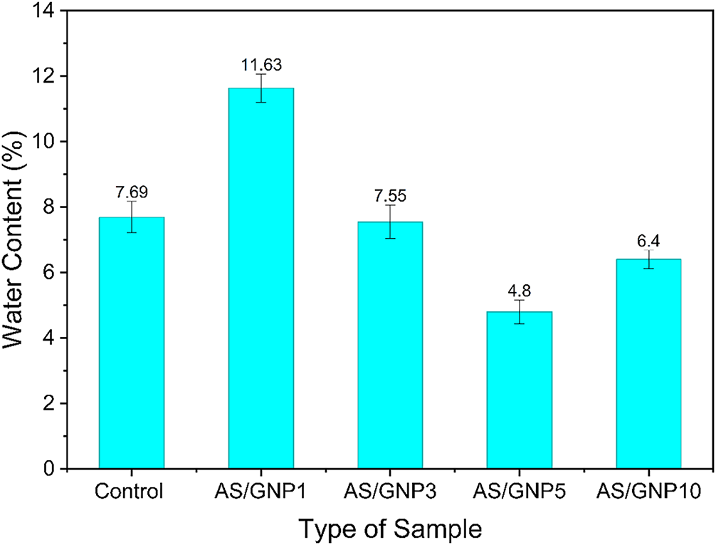
Figure 6. Graph of water content with different loadings of the GNP film sample
However, when the GNP content was increased to 3% (AS/GNP3), the water content decreased to 7.55%, which is close to the control value. This suggests that better dispersion of GNP at this concentration could enhance barrier properties by reducing the availability of free hydroxyl groups for water interaction. The most significant reduction was observed at 5% GNP (AS/GNP5), where the water content dropped to 4.8%. This reduction indicates that higher filler content restricts water penetration by forming a more compact structure and improving interfacial interactions, which reduces the mobility of starch chains and limits water absorption [47].
Interestingly, at 10% GNP (AS/GNP10), the water content slightly increased to 6.4%, which is higher than AS/GNP5 but still lower than the control. This increase could be attributed to possible nanoplatelet agglomeration at high loading, which may create microvoids or structural irregularities, allowing some water molecules to be absorbed [48]. Nonetheless, the overall water uptake remained reduced compared to the neat starch film.
Figure 7 demonstrated results of the maximum displacement show that the addition of GNP produced a significant influence on the plasticity of films made of AS. The control sample had a displacement value of 4.44 mm which was used as a baseline in assessment. In the case where 1% GNP was used (AS/GNP1), the highest displacement was reduced drastically to 3.11 mm. This decrement is an indication that a low concentration of GNP initially limits the mobility of the polymer chains and enhances their rigidity resulting in an inflexible product [49].
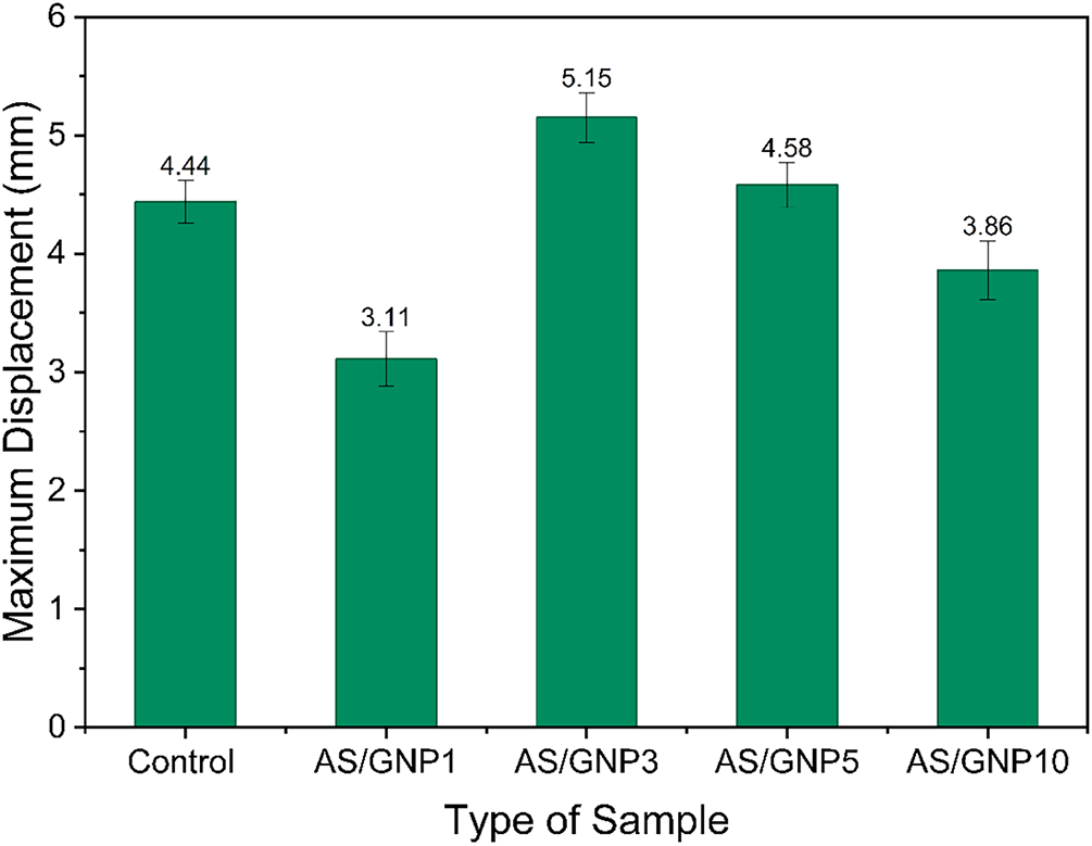
Figure 7. Graph of maximum displacement with different loadings of GNP film
Interestingly, an additional increase in the GNP content to 3% (AS/GNP3) improved the maximum displacement to 5.15 mm, the largest of all samples. It means that at such concentration GNP was distributed well within the starch structure, which means the stress transfer was enhanced as well as ductility [50]. The polymer chains could bend and bend without fracturing effectively implying the optimum filler loading at this stage [51].
At the 5% loading (AS/GNP5) the displacement was marginally greater than the control (4.58 mm) but less than AS/GNP3. This is an indication of some loss of flexibility, probably because of the onset of the nanoplatelet aggregation and hence limits the movement of the chains. The pattern persisted in the highest loading of AS/GNP10 with the displacement decreasing to 3.86 mm. The decreased high GNP content performance could be explained by the low dispersion and agglomeration of the nanoplatelets resulting in stress concentration points that restrict ductility [52].
Figure 8 shows Young’s modulus results demonstrates that the addition of GNP significantly increased the film stiffness of starch (arrowroot) in the presence of starch. The control sample had a modulus of 67.9 MPa, which is relatively low rigidity of pure starch films. With a 1 percent GNP added (AS/GNP1) the modulus shot up to 126.3 MPa, or almost twice as high. Such a critical increase suggests that there was good interfacial bonding between the starch backbone and GNP even in low concentrations that actually limited the mobility of polymer chains and strengthened the film framework [53].
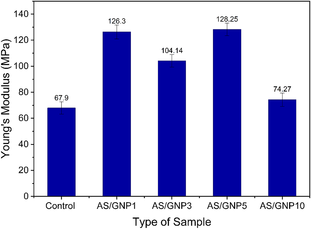
Figure 8. Graph of young’s modulus with different loadings of GNP
The modulus was reduced a bit, at 3% loading (AS/GNP3), to 104.14 MPa, still higher than the control. The decrease indicates that partial nanoplatelet aggregation might have taken place at a high concentration leading to inefficient stress transfer and reduced stiffness relative to AS/GNP1. Interestingly, modulo peaked at 5 percent GNP loading (AS/GNP5) of 128.25 MPa, as compared to all other samples. This implies that even at this concentration, the nanoplatelets remained well dispersed, which offered an optimal reinforcing effect to maximize rigidity [54].
Nevertheless, on further loading to 10 percent (AS/GNP10), the modulus was significantly reduced to 74.27 MPa, which was nearly the same as the control. This decrease may be explained by the fact that the extent of aggregation of nanoparticles is high in the case of high loadings and introduces cracks and discontinuities into the composite. These agglomerates break homogenous distribution of stress, and hence they weaken the reinforcing efficiency of the GNP [55].
Figure 9 shows the tensile strength against the GNP loadings. The lowest tensile strength was registered in the control film of 0.99 MPa, which demonstrates how intrinsically weak pure starch-based films are since they are brittle and have a low stress bearing capacity. The tensile strength increased marginally when 1% GNP was added (AS/GNP1) to reach 1.19 MPa, indicating that even a low content of GNP can promote stress transfer between filler and starch matrix [55].
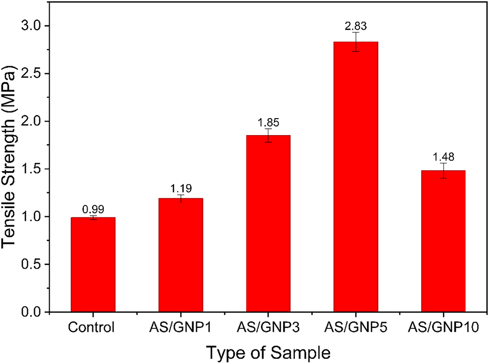
Figure 9. Graph of tensile Strength against the graphene nanoplatelet loading
With a loading of tensile strength of 3% GNP (AS/GNP3) tensile strength increased further to 1.85 MPa, which was almost doubled at the same point relative to the control. This rise indicates that there was good dispersion of the nanoplatelets because it is probable that interfacial adhesion was good and the polymer chains could not slip under the tensile stress. The maximum tensile strength was realized at 5 percent loading (AS/GNP5) which was 2.83 MPa. This notable increase shows that at this level, GNP reinforcement was most efficient, as the ratio between filler dispersion and matrix interaction enabled the film to sustain more applied forces until it broke [56].
Nevertheless, with the maximum concentration (AS/GNP10), tensile strength reduced to 1.48 MPa, but this was also greater than the control. This decrease can only be attributed to aggregation of nanoplatelets that causes the composite to be weak as it creates sites of stress concentration and stress transfer among the matrix is lowered [57]. This agglomeration interferes with the uniformity of the film structure resulting into early failure under tension [58].
Figure 10 bar chart shows the elongation at break (%) AS/GNP composite films at varying GNP loadings in relation to the control film. The control sample had a break elongation of 12.25% which means that the material is ductile. With 1 percent GNP added (AS/GNP1), elongation at break was much lower at 7.67 percent, indicating that the low weight of GNP loading can limit the movement of polymer chain because of inflexible filler-matrix interaction, resulting in a more brittle structure [59].
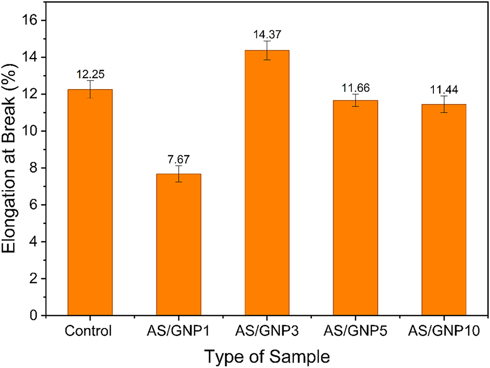
Figure 10. Graph Elongation at Break (%) against the GNP loading (%)
Surprisingly, the highest value of elongation of 14.37 percent was obtained with the addition of 3 percent GNP (AS/GNP3) which was higher than the control. Such an enhancement suggests that at an optimum loading, GNPs can serve as stress-transfer agents, enhancing better dispersion and interaction with the starch matrix, and thus increasing flexibility and toughness [60]. The enhanced interfacial bonding could be beneficial in increasing load distribution so the film can stretch more to failure [61].
Further additions of GNP content to 5% (AS/GNP5) and 10% (AS/GNP10) however led to decreased elongation values of 11.66% and 11.44, respectively, both lower than the control and AS/GNP3. This drop can be explained by the presence of nanoplatelet agglomeration at greater concentrations, which can create stress concentration regions and prevent the mobility of polymer chains [62]. These effects cause the ductile property of the composite to be less stretchable.
3.3. Field emission scanning electron microscope (FESEM)
Figure 11 shows the FESEM micrographs also explain the morphological change in the AS/GNP composite films by increasing the graphene nanoplatelet (GNP) loading into it. In the Figure 11a of the control film, the broken surface is relatively rough, with clear cracks and clear holes. These cracks represent brittleness and poor internal bonding whereas the existence of these voids reflects the incompleteness of starch filling and the incompleteness of packing inside the starch. The structure is seen as less compact, which is associated with the low density seen in the control sample [63].
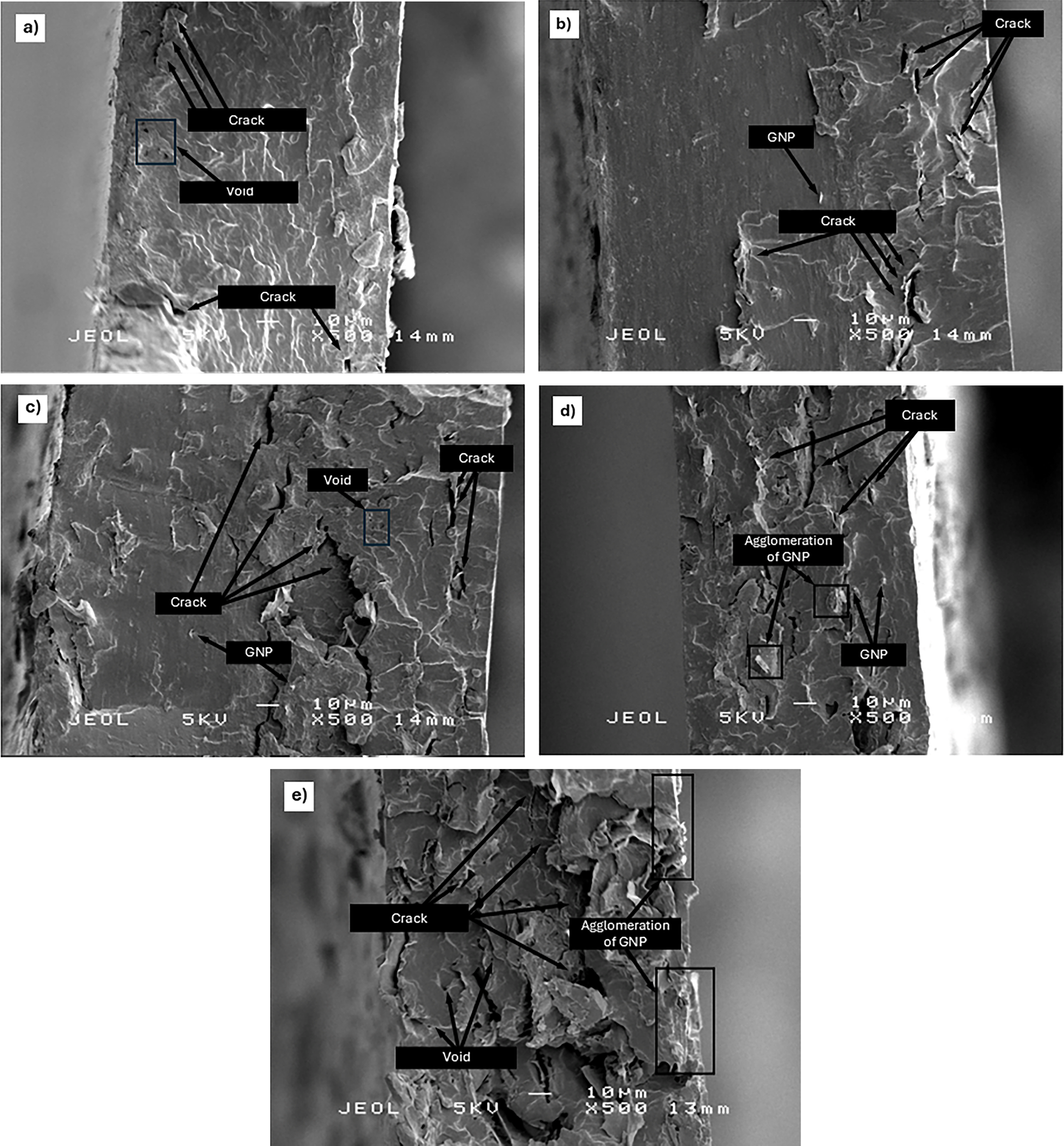
Figure 11. FESEM micrographs of AS/GNP films: (a) Control, (b) AS/GNP1 (c) AS/GNP3, (d) AS/GNP5, (e) AS/GNP10
Figure 11b, which is associated with low GNP loading (AS/GNP1), it is possible to see graphene nanoplatelets, which are embedded in the matrix. The morphology of the surface is made more compact when compared to the control, but cracks can still be observed. The incorporation of GNP implies strengthening of the starch network which brings about the strengthening of the structure. The cracks are seen to be further driven and smaller in area, suggesting that the scattered nanoplatelets could hinder percolation of these cracks to some extent [64].
Figure 11c, which is probably AS/GNP3, represents a more integrated structure where GNP is more cosmetically distributed in the matrix. The surface is denser and more consolidated, though there are still some voids and cracks. The interrelation between AS and GNP is seen to be more powerful through the smaller size and the frequency of voids. The continuity of the matrix is higher, which justifies the density results obtained in the previous study, which showed that the density was substantially increased at this composition.
Figure 11d, which shows increased GNP loading (AS/GNP5), shows that the effects of GNP agglomeration are visible. The general structure is small, but localized concentrations of graphene nanoplatelets can be seen. Such agglomerated areas can be a stress concentration forming locations and hence a starting point of cracks [65]. The morphology shows that, despite the fact that reinforcement still exists, the dispersion quality can start to decline at this level of loading.
Lastly, Figure 11e with the highest GNP loading (AS/GNP10) shows stronger agglomeration, cracks, and few gaps can also be seen. The rounded-off GNP dispersions indicate inefficiency of dispersion at high filler content. Such agglomerates have the ability to interfere with the uniformity of matrix and prevent further densification [66]. The microstructure is ambiguous that though the composite is still denser than the control, overloading GNP could lead to the loss of homogeneity and mechanical performance because of aggregation of fillers [67].
In sum, the FESEM analysis indicates that with an increased amount of GNP, porous, crack-prone pure starch matrix was transformed to a denser reinforced composite. At a certain point, however, under the ideal loading agglomeration effects become visible, which can reduce the effect of the reinforcement and explain the plateau witnessed by the density results.
3.4. Differential scanning calorimetry (DSC)
Figure 12 represents the differential scanning calorimetry (DSC) thermograms describing the thermal behavior of the control material and the AS/GNP composite films over a wide temperature range. At low-temperature conditions (below 100°C), all specimens show a small endothermic deviation, which is usually attributed to moisture evaporation or the loss of physically bound water. The composites show changes in intensity compared to the control, indicating that the addition of graphene nanoplatelets alters moisture retention and interactions within the matrix [68].
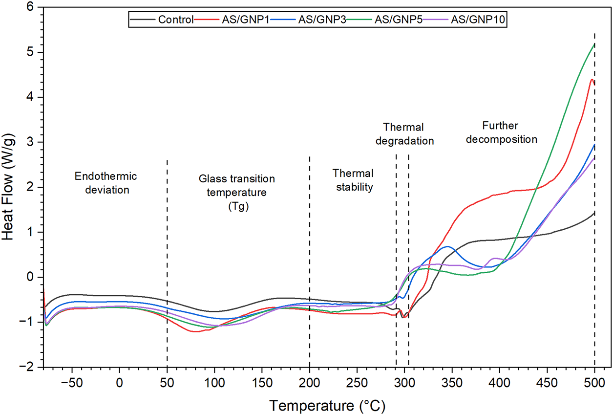
Figure 12. Differential scanning calorimetry (DSC) curves of AS/GNP films
A slight shift is also observed in the glass transition temperature (Tg) in the mid-temperature range (around 80°C–120°C) when GNP is added. The AS/GNP composites show a minor change in Tg compared to the control, meaning that polymer chain movement is restricted due to changes in interfacial interaction between amylose starch (AS) and GNP. This observation suggests that graphene nanoplatelets act as reinforcing fillers that restrict segmental movement of the starch chains and increase matrix rigidity [69].
Between approximately 200°C and 300°C, the thermograms show a relatively stable region before significant thermal degradation begins. The composites, especially the medium GNP-loaded samples (AS/GNP3 and AS/GNP5), appear to display better thermal stability compared to the control. This improvement can be attributed to the barrier effect of GNP, which slows heat transfer and delays thermal decomposition [70].
Thermal decomposition and further degradation occur significantly above 300°C. Heat flow increases markedly at elevated temperatures approaching 500°C and above. Differences among the composites become more pronounced in this region. Optimized GNP loading produces moderated decomposition behavior, while excessive loading may result in variations attributed to agglomeration effects. Overall, the DSC data indicate that incorporation of GNP enhances thermal stability up to an optimal loading, which correlates with improved structural compactness and interfacial interaction within the AS matrix.
Figure 13 shows the voltage (V–I) curves illustrate the microelectrical response of the control and AS/GNP films as the applied current is steadily increased. In all specimens, voltage shows a monotonically increasing dependence on current, confirming typical resistive behavior. However, noticeable changes in slope and absolute voltage magnitude are observed among the samples, indicating variations in electrical performance resulting from the addition of graphene nanoplatelets (GNPs).
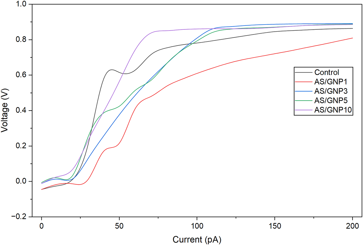
Figure 13. Voltage vs. Current of AS/GNP films
The control sample shows a moderate, nearly linear increase in voltage with current, reaching approximately 0.86 V at 200 pA. This observation implies a stable but relatively lower electrical response compared to the composite samples. Conversely, the AS/GNP1 sample exhibits the lowest recorded voltages across the studied current range, suggesting reduced electrical efficiency at low GNP loading. This decreased performance can be explained by the insufficient formation of conductive pathways at low nanoplatelet concentration [71].
A significant improvement in voltage response is observed at intermediate GNP loadings, particularly for AS/GNP3 and AS/GNP5. These samples display steeper V–I slopes and higher voltage values compared to both the control and AS/GNP1, indicating better dispersion of GNP within the polymer matrix. This enhanced dispersion promotes improved charge transport and formation of a more effective conductive network [72]. Among them, AS/GNP3 and AS/GNP5 show comparable high-voltage outputs, suggesting that this loading range represents an optimal balance between filler content and dispersion quality.
At the highest loading (AS/GNP10), voltage increases rapidly at low currents and reaches comparable or slightly higher output at moderate currents relative to the other composites. However, the curve levels off at higher current values, indicating a saturation effect. This behavior may be attributed to filler agglomeration at high loading, which limits further development of conductive pathways [73].
Overall, the results indicate that GNP incorporation enhances the electrical performance of the AS matrix up to an optimal loading. Intermediate GNP levels provide the most stable and efficient electrical performance, while excessive loading results in diminishing returns due to agglomeration-induced limitations on network formation.
The given study establishes how graphene nanoplatelet (GNP)-reinforced arrowroot thermoplastic starch (AS) composite films can be produced successfully with considerably high multifunctional properties, which make them effective in flexible electronics. The systematic examination of the physical, mechanical, morphological, thermal, and electrical properties establishes that incorporation of GNPs changes the structure–property relation of the starch matrix fundamentally. The filler loading had a linear relationship with film thickness and density, with an optimum at 1 wt% as a result of improved packing before decreasing at higher filler concentrations due to agglomeration of nanoplatelets. Mechanical analysis showed that there was indeed a strong reinforcement effect of tensile strength and Young’s modulus, which reached extreme values at 5 wt% of GNP (2.83 and 128.25 MPa, respectively), which was a significant improvement on neat AS, and elongation at break maximized at 3 wt%. These results were supported by FESEM images, micro-voids, which showed uniform dispersion and compact morphology at low to moderate loadings, but excess filler content led to agglomeration, micro-voids, and stress-concentration regions, which weakened performance. The thermal analysis revealed improved thermal stability at intermediate loadings because of the limitation in the mobility of the polymer chain and the formation of barriers by well-dispersed nanoplatelets. The conducting behavior was also demonstrated to be enhanced in the range of 3–5 wt%, and electrical characterization showed that 3–5 wt% formed functional percolative networks, and above this, a saturation effect is seen because of aggregation. Together, the findings prove that the controlled GNP incorporation, especially in the 3–5 per cent range, allows the rational construction of high-performance, biodegradable, and economical AS-based biocomposites. The paper has contributed to the development of understanding of the reinforcement approaches of the starch–graphene system, as well as placed optimized AS/GNP films as potential materials for future sustainable flexible electronic sensors and devices.
Acknowledgement: The authors wish to thank The Ministry of Higher Education Malaysia (MoHE) for financing this work under the Fundamental Research Grant Scheme (FRGS), with project code of FRGS/1/2023/TK09/UPM/01/3/5540599.
Funding Statement: This research was supported by the Fundamental Research Grant Scheme (FRGS) under the Ministry of Higher Education Malaysia, with the project code FRGS/1/2023/TK09/UPM/01/3/5540599.
Author Contributions: A. H. M. Firdaus: Writing—original draft, writing—review & editing, data curation, resources, methodology, and conceptualization; S. M. Sapuan: Supervision, funding acquisition, conceptualization; E. S. Zainudin: Supervision; A. Atiqah: Supervision; Divesh Makendren: Writing—review & editing, data curation, resources, methodology, and conceptualization; Vasi Uddin Siddiqui: Supervision. All authors reviewed and approved the final version of the manuscript.
Availability of Data and Materials: Data available on request from the authors. The data that supports the findings of this study are available from the corresponding author, upon reasonable request.
Ethics Approval: Not applicable.
Conflicts of Interest: The authors declare no conflicts of interest.
How to Cite this Article
References
- Reddy MSB, Ponnamma D, Choudhary R, Sadasivuni KK. A comparative review of natural and synthetic biopolymer composite scaffolds. Polymers. 2021;13(7):1105. doi:10.3390/polym13071105; 33808492 DOI
- Prakash SO, Sahu P, Madhan M, Santhosh AJ. A review on natural fibre-reinforced biopolymer composites: properties and applications. Int J Polym Sci. 2022;2022:7820731. doi:10.1155/2022/7820731. DOI
- Kumar A, Mishra RK, Verma K, Aldosari SM, Maity CK, Verma S, et al. A comprehensive review of various biopolymer composites and their applications: from biocompatibility to self-healing. Mater Today Sustain. 2023;23(8):100431. doi:10.1016/j.mtsust.2023.100431. DOI
- Witasari LD, Nisrina S, Yani AIT, Heryadi AA, Pranoto Y. Characterization of porous starch produced from arrowroot (Maranta arundinacea L.) by enzymatic hydrolysis with α-amylase and glucoamylase. Carbohydr Polym Technol Appl. 2024;7(1):100445. doi:10.1016/j.carpta.2024.100445. DOI
- Khan A, Sapuan SM, Husna N. 11–A review on arrowroot fiber reinforced polymer composites. In: Sapuan SM, Abral H, Jamal T, Thakur VK, Nazrin A, Sherwani SFK, editors. Plant tuber and root-based biocomposites: development, characterization, and applications. Sawston, UK: Woodhead Publishing; 2025. p. 227–38. doi:10.1016/B978-0-443-14126-3.00011-4. DOI
- Brito V, Nascimento R, Narcisa-Oliveira J, Joffer N, Fattori A, Cereda M, et al. Arrowroot (Maranta arundinacea L.): botany, horticulture, and uses. In: Horticultural reviews. Hoboken, NJ, USA: John Wiley & Sons, Inc.; 2021. p. 233–74. doi:10.1002/9781119750802.ch4. DOI
- Ding J, Zhao H, Yu H. Bioinspired strategies for making superior graphene composite coatings. Chem Eng J. 2022;435(9):134808. doi:10.1016/j.cej.2022.134808. DOI
- Yee K, Ghayesh MH. A review on the mechanics of graphene nanoplatelets reinforced structures. Int J Eng Sci. 2023;186(5):103831. doi:10.1016/j.ijengsci.2023.103831. DOI
- Yahya MN, Norddin MNAM, Ismail I, Rasol AAA, Risal AR, Yakasai F, et al. Graphene nanoplatelet surface modification for rheological properties enhancement in drilling fluid operations: a review. Arab J Sci Eng. 2024;49(6):7751–81. doi:10.1007/s13369-023-08458-5. DOI
- Bilisik K, Akter M. Graphene nanoplatelets/epoxy nanocomposites: a review on functionalization, characterization techniques, properties, and applications. J Reinf Plast Compos. 2022;41(3–4):99–129. doi:10.1177/07316844211049277. DOI
- Razaq A, Bibi F, Zheng X, Papadakis R, Jafri SHM, Li H. Review on graphene-, graphene oxide-, reduced graphene oxide-based flexible composites: from fabrication to applications. Materials. 2022;15(3):1012. doi:10.3390/ma15031012; 35160958 DOI
- Urade AR, Lahiri I, Suresh KS. Graphene properties, synthesis and applications: a review. JOM. 2023;75(3):614–30. doi:10.1007/s11837-022-05505-8; 36267692 DOI
- Aaliya B, Sunooj KV, Lackner M. Biopolymer composites: a review. Int J Biobased Plast. 2021;3(1):40–84. doi:10.1080/24759651.2021.1881214. DOI
- Bari E, Sistani A, Morrell JJ, Pizzi A, Akbari MR, Ribera J. Current strategies for the production of sustainable biopolymer composites. Polymers. 2021;13(17):2878. doi:10.3390/polym13172878; 34502919 DOI
- Rahayu ES, Widadie F, Irianto H, Handayani SM, Setyowati, Sundari MT. Strategies to strengthen arrowroot production as a land cover crop and improve farmers’ economy. IOP Conf Ser Earth Environ Sci. 2025;1438(1):012004. doi:10.1088/1755-1315/1438/1/012004. DOI
- Mohd Nizam NH, Mohammad Rawi NF, Mhd Ramle SF, Abd Aziz A, Abdullah CK, Rashedi A, et al. Physical, thermal, mechanical, antimicrobial and physicochemical properties of starch based film containing aloe vera: a review. J Mater Res Technol. 2021;15(4):1572–89. doi:10.1016/j.jmrt.2021.08.138. DOI
- Nazrin A, Ilyas RA, Rajeshkumar L, Hazrati KZ, Jamal T, Mahardika M, et al. Lignocellulosic fiber-reinforced starch thermoplastic composites for food packaging application: a review of properties and food packaging abetted with safety aspects. Food Packag Shelf Life. 2025;47:101431. doi:10.1016/j.fpsl.2025.101431. DOI
- Yusuf J, Firdaus AHM, Sapuan SM, Rashid U, Ilyas RA, Hassan MR, et al. Nanocellulose-graphene hybrid composites: fabrication, characterization, applications and environmental impact. Int J Biol Macromol. 2024;282(Pt 5):137244. doi:10.1016/j.ijbiomac.2024.137244; 39505165 DOI
- Jailani A, Hidzer MH, Firdaus AHM, Sapuan SM, Zainudin ES, Atiqah A, et al. Enhancing polyvinyl alcohol (PVA) nanocomposites: key properties, applications and challenges in advanced engineering. Def Technol. 2026;55:11–29. doi:10.1016/j.dt.2025.05.020. DOI
- Ilyas RA, Sapuan SM, Norrrahim MNF, Yasim-Anuar TAT, Kadier A, Kalil MS, et al. Nanocellulose/starch biopolymer nanocomposites: processing, manufacturing, and applications. In: Advanced processing, properties, and applications of starch and other bio-based polymers. Amsterdam, The Netherlands: Elsevier; 2020. p. 65–88. doi:10.1016/b978-0-12-819661-8.00006-8. DOI
- Binaymotlagh R, Chronopoulou L, Palocci C. An overview of biopolymer-based graphene nanocomposites for biotechnological applications. Materials. 2025;18(13):2978. doi:10.3390/ma18132978; 40649466 DOI
- Rahmat NF, Sajab MS, Afdzaluddin AM, Chia CH, Ding G. Enhancing the electrochemical properties of biopolymer composites using starch-graphene nanoplatelets. Polym Compos. 2024;45(16):14905–15. doi:10.1002/pc.28809. DOI
- Gürler N, Torğut G. Graphene-reinforced potato starch composite films: improvement of mechanical, barrier and electrical properties. Polym Compos. 2021;42(1):173–80. doi:10.1002/pc.25816. DOI
- Muhammad Firdaus AH, Sapuan SM, Mohd Afdzaluddin A, Al-Oqla FM. A review of graphene biopolymer composite in piezoelectric sensor applications. Phys Sci Rev. 2024;9(12):3639–65. doi:10.1515/psr-2024-0080. DOI
- Chen Y, Guo Z, Das R, Jiang Q. Starch-based carbon nanotubes and graphene: preparation, properties and applications. ES Food Agrofor. 2020;2:13–21. doi:10.30919/esfaf1111. DOI
- Ghaffarkhah A, Hosseini E, Kamkar M, Sehat AA, Dordanihaghighi S, Allahbakhsh A, et al. Synthesis, applications, and prospects of graphene quantum dots: a comprehensive review. Small. 2022;18(2):e2102683. doi:10.1002/smll.202102683; 34549513 DOI
- Ahmad Izaddin Sheikh Mohd Ghazali S, Fatimah I, Zamil ZN, Zulkifli NN, Adam N. Graphene quantum dots: a comprehensive overview. Open Chem. 2023;21(1):20220285. doi:10.1515/chem-2022-0285. DOI
- Nogueira GF, Fakhouri FM, de Oliveira RA. Extraction and characterization of arrowroot (Maranta arundinaceae L.) starch and its application in edible films. Carbohydr Polym. 2018;186(3):64–72. doi:10.1016/j.carbpol.2018.01.024; 29456010 DOI
- Boonphayak P, Muenyong N, Chinchao R, Khansumled S. Development of a biodegradable cassava starch biofilm based on a combination of plasticizers with bio-SiO2 extracted from sugarcane leaves. Starch Stärke. 2025;77(1):2300164. doi:10.1002/star.202300164. DOI
- Hazrati KZ, Sapuan SM, Zuhri MYM, Jumaidin R. Preparation and characterization of starch-based biocomposite films reinforced by Dioscorea hispida fibers. J Mater Res Technol. 2021;15:1342–55. doi:10.1016/j.jmrt.2021.09.003. DOI
- Ilyas RA, Sapuan SM, Ishak MR, Zainudin ES. Development and characterization of sugar palm nanocrystalline cellulose reinforced sugar palm starch bionanocomposites. Carbohydr Polym. 2018;202:186–202. doi:10.1016/j.carbpol.2018.09.002; 30286991 DOI
- Sanyang ML, Sapuan SM, Jawaid M, Ishak MR, Sahari J. Effect of plasticizer type and concentration on physical properties of biodegradable films based on sugar palm (Arenga pinnata) starch for food packaging. J Food Sci Technol. 2016;53(1):326–36. doi:10.1007/s13197-015-2009-7; 26787952 DOI
- Tarique J, Sapuan SM, Khalina A. Effect of glycerol plasticizer loading on the physical, mechanical, thermal, and barrier properties of arrowroot (Maranta arundinacea) starch biopolymers. Sci Rep. 2021;11(1):13900. doi:10.1038/s41598-021-93094-y; 34230523 DOI
- Tarique J, Zainudin ES, Sapuan SM, Ilyas RA, Khalina A. Physical, mechanical, and morphological performances of arrowroot (Maranta arundinacea) fiber reinforced arrowroot starch biopolymer composites. Polymers. 2022;14(3):388. doi:10.3390/polym14030388; 35160378 DOI
- ASTM F2251–13. Standard test method for thickness measurement of flexible packaging material. West Conshohocken, PA, USA: ASTM International; 2018.
- Liu F, Zhang X, Xiao X, Duan Q, Bai H, Cao Y, et al. Improved hydrophobicity, antibacterial and mechanical properties of polyvinyl alcohol/quaternary chitosan composite films for antibacterial packaging. Carbohydr Polym. 2023;312:120755. doi:10.1016/j.carbpol.2023.120755; 37059517 DOI
- ASTM D882-02. Standard test method for tensile properties of thin plastic sheeting. West Conshohocken, PA, USA: ASTM International; 2002.
- Li R, Liu C, Ma J. Studies on the properties of graphene oxide-reinforced starch biocomposites. Carbohydr Polym. 2011;84(1):631–7. doi:10.1016/j.carbpol.2010.12.041. DOI
- Sirviö JA, Kolehmainen A, Liimatainen H, Niinimäki J, Hormi OEO. Biocomposite cellulose-alginate films: promising packaging materials. Food Chem. 2014;151:343–51. doi:10.1016/j.foodchem.2013.11.037; 24423542 DOI
- Pongjanyakul T, Puttipipatkhachorn S. Alginate-magnesium aluminum silicate composite films: effect of film thickness on physical characteristics and permeability. Int J Pharm. 2008;346(1–2):1–9. doi:10.1016/j.ijpharm.2007.05.058; 17611056 DOI
- Rhim JW, Wu Y, Weller CL, Schnepf M. Physical characteristics of a composite film of soy protein isolate and propyleneglycol alginate. J Food Sci. 1999;64(1):149–52. doi:10.1111/j.1365-2621.1999.tb09880.x. DOI
- Blalock JS, Holmes RG, Rueggeberg FA. Effect of temperature on unpolymerized composite resin film thickness. J Prosthet Dent. 2006;96(6):424–32. doi:10.1016/j.prosdent.2006.09.022; 17174660 DOI
- Cataldi P, Bayer IS, Nanni G, Athanassiou A, Bonaccorso F, Pellegrini V, et al. Effect of graphene nano-platelet morphology on the elastic modulus of soft and hard biopolymers. Carbon. 2016;109(5):331–9. doi:10.1016/j.carbon.2016.08.026. DOI
- Vilcinskas K, Norder B, Goubitz K, Mulder FM, Koper GJM, Picken SJ. Tunable order in alginate/graphene biopolymer nanocomposites. Macromolecules. 2015;48(22):8323–30. doi:10.1021/acs.macromol.5b01380. DOI
- Abdullah NM, Rus AZM, Abdullah MFL. Synergistic influence of graphite on biopolymer composites properties. J Teknol. 2015;77(32):11–9. doi:10.11113/jt.v77.6981. DOI
- Fani K, Farahpour MR, Tabatabaei ZG. SeO32−/graphene oxide hybridized to multicomponent biopolymer based the scaffold to accelerate bone defect regeneration. Ceram Int. 2022;48(24):37212–22. doi:10.1016/j.ceramint.2022.08.298. DOI
- Vilcinskas K, Zlopasa J, Jansen KMB, Mulder FM, Picken SJ, Koper GJM. Water sorption and diffusion in (reduced) graphene oxide-alginate biopolymer nanocomposites. Macro Mater Eng. 2016;301(9):1049–63. doi:10.1002/mame.201600154. DOI
- Han Y, Li K, Chen H, Li J. Properties of soy protein isolate biopolymer film modified by graphene. Polymers. 2017;9(8):312. doi:10.3390/polym9080312; 30970989 DOI
- Cai K, Wang X, Yu C, Zhang J, Tu S, Feng J. Enhancing the mechanical properties of PBAT/thermoplastic starch (TPS) biodegradable composite films through a dynamic vulcanization process. ACS Sustain Chem Eng. 2024;12(4):1573–83. doi:10.1021/acssuschemeng.3c06847. DOI
- Ahmed J, Mulla MZ, Vahora A, Bher A, Auras R. Polylactide/graphene nanoplatelets composite films: impact of high-pressure on topography, barrier, thermal, and mechanical properties. Polym Compos. 2021;42(6):2898–909. doi:10.1002/pc.26023. DOI
- Li L, Li M, Zhang Z, Qin Y, Shui X, Xia J, et al. Robust composite film with high thermal conductivity and excellent mechanical properties by constructing a long-range ordered sandwich structure. J Mater Chem A. 2022;10(18):9922–31. doi:10.1039/d2ta00975g. DOI
- Shui YJ, Yao WH, Lin JH, Zhang Y, Yu Y, Wu CS, et al. Enhancing polyvinyl alcohol nanocomposites with carboxy-functionalized graphene: an in-depth analysis of mechanical, barrier, electrical, antibacterial, and chemical properties. Polymers. 2024;16(8):1070. doi:10.3390/polym16081070; 38674991 DOI
- Liu B, Pavlou C, Wang Z, Cang Y, Galiotis C, Fytas G. Determination of the elastic moduli of CVD graphene by probing graphene/polymer Bragg stacks. 2D Mater. 2021;8(3):035040. doi:10.1088/2053-1583/abfedb. DOI
- Han S, Wang P, Zhou Y, Meng Q, Aakyiir M, Ma J. Flexible, mechanically robust, multifunctional and sustainable cellulose/graphene nanocomposite films for wearable human-motion monitoring. Compos Sci Technol. 2022;230:109451. doi:10.1016/j.compscitech.2022.109451. DOI
- Zhang S, Sun H, Lan T, Bai Z, Liu X. Facile preparation of graphene film and sandwiched flexible poly(arylene ether nitrile)/graphene composite films with high EMI shielding efficiency. Compos Part A Appl Sci Manuf. 2022;154:106777. doi:10.1016/j.compositesa.2021.106777. DOI
- Koutroumanis N, Manikas AC, Pappas PN, Anagnostopoulos G, Galiotis C. Interfacial properties and mechanical performance of hybrid graphene/carbon fibre composites. Mater Today Commun. 2024;41:110458. doi:10.1016/j.mtcomm.2024.110458. DOI
- Ponnusamy PG, Sundaram J, Mani S. Preparation and characterization of citric acid crosslinked chitosan-cellulose nanofibrils composite films for packaging applications. J Appl Polym Sci. 2022;139(17):52017. doi:10.1002/app.52017. DOI
- Kaewprachu P, Jaisan C, Klunklin W, Phongthai S, Rawdkuen S, Tongdeesoontorn W. Mechanical and physicochemical properties of composite biopolymer films based on carboxymethyl cellulose from young Palmyra Palm fruit husk and rice flour. Polymers. 2022;14(9):1872. doi:10.3390/polym14091872; 35567041 DOI
- Ali MF, Hossain MS, Ahmed S, Sarwaruddin Chowdhury AM. Fabrication and characterization of eco-friendly composite materials from natural animal fibers. Heliyon. 2021;7(5):e06954. doi:10.1016/j.heliyon.2021.e06954; 34027163 DOI
- Zhang X, Li J, Chen Z, Pang C, He S, Lin J. Study on thermal-oxidative aging properties of ethylene-propylene-diene monomer composites filled with silica and carbon nanotubes. Polymers. 2022;14(6):1205. doi:10.3390/polym14061205; 35335536 DOI
- Li Z, Xu W, Song K, Zhang J, Liu Q, El-Bahy ZM, et al. Cellulose nanofibers-based composite film with broadening MXene layer spacing and rapid moisture separation for humidity sensing and humidity actuators. Int J Biol Macromol. 2024;278(Pt 1):134383. doi:10.1016/j.ijbiomac.2024.134383; 39098695 DOI
- Lv Y, Li P, Cen L, Wen F, Su R, Cai J, et al. Gelatin/carboxymethylcellulose composite film combined with photodynamic antibacterial: new prospect for fruit preservation. Int J Biol Macromol. 2024;257(Pt 1):128643. doi:10.1016/j.ijbiomac.2023.128643; 38061514 DOI
- Mruthyunjayappa KC, Paramashivaiah SA, Mallikarjunappa EK, Padre SM, Gurumurthy SC, Surabhi S, et al. A combined experimental and computational study of flexible polyvinyl alcohol (PVA)/graphene oxide (GO) nanocomposite films for superior UV shielding with improved mechanical properties. Mater Today Commun. 2023;35:105662. doi:10.1016/j.mtcomm.2023.105662. DOI
- Kumar YR, Deshmukh K, Ali MMN, Abhijay G, Al-Onazi WA, Al-Mohaimeed AM, et al. Structure, morphology and modelling studies of polyvinylalcohol nanocomposites reinforced with nickel oxide nanoparticles and graphene quantum dots. Environ Res. 2022;203:111842. doi:10.1016/j.envres.2021.111842; 34363804 DOI
- Yousif RS. Examination of the structural, morphological, and self-cleaning characteristics of graphene oxide-based nanocomposite thin films. Results Phys. 2025;76:108410. doi:10.1016/j.rinp.2025.108410. DOI
- Nandee R, Chowdhury MA, Hossain N, Rana MM, Mobarak MH, Khandaker MR. Surface topography and surface morphology of graphene nanocomposite by FESEM, EDX and AFM analysis. Nano Struct Nano Objects. 2024;38(8):101170. doi:10.1016/j.nanoso.2024.101170. DOI
- Hosseini NS, Hasanzadeh J, Abdolahzadeh Ziabari A. A comparative study on the structure, morphology and ethanol sensitivity of ZnO thin films alloyed with graphene oxide and reduced graphene oxide. Opt Quantum Electron. 2022;54(10):662. doi:10.1007/s11082-022-04029-4. DOI
- Nurazzi NM, Abdullah N, Norrrahim MNF, Kamarudin SH, Ahmad S, Shazleen SS, et al. Thermogravimetric analysis (TGA) and differential scanning calorimetry (DSC) of PLA/cellulose composites. In: Polylactic acid-based nanocellulose and cellulose composites. Boca Raton, FL, USA: CRC Press; 2022. p. 145–64. doi:10.1201/9781003160458-7. DOI
- Ilyas RA, Sapuan SM, Asyraf MRM, Atikah MSN, Ibrahim R, Norrrahim MNF, et al. Mechanical and dynamic mechanical analysis of bio-based composites. In: Mechanical and dynamic properties of biocomposites. Hoboken, NJ, USA: John Wiley & Sons, Inc.; 2021. p. 49–76. doi:10.1002/9783527822331.ch3. DOI
- Jumaidin R, Abdul Rahman AH, Sapuan SM, Rushdan AI. Effect of sugarcane bagasse on thermal and mechanical properties of thermoplastic cassava starch/beeswax composites. Phys Sci Rev. 2024;9(1):1–15. doi:10.1515/psr-2022-0047. DOI
- Azzra NA, Afdzaluddin A, Jalar A, Ismail AG, Dashtizadeh Z. Physical and electrical properties of sustainable substrate thermoplastic starch/nanocellulose fibre/stannous oxide. J Adv Res Appl Sci Eng Technol. 2023;36(1):93–101. doi:10.37934/araset.36.1.93101. DOI
- Romano S, Brugnoli B, De Santis S, Rocco D, Frezza C, Sotgiu G, et al. Dicationic ionic liquids as antibacterial and conductive plasticizers: effect of cationic structures on starch film properties for flexible electronics. ACS Appl Bio Mater. 2025;8(9):8297–309. doi:10.1021/acsabm.5c01229; 40884812 DOI
- Rugmini R, Chandana BDS, Sekhar KC, Sugumaran S. Naked-eye detection of Fe3+ and photothermal applications of flexible and sustainable banana pith stabilized silver nanoparticle-rice starch composite. Emergent Mater. 2025;8(4):2545–59. doi:10.1007/s42247-024-00905-9. DOI